The role and use of the ball valve
The function of the ball valve:
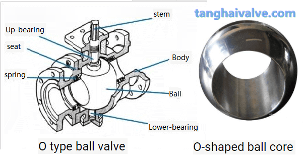
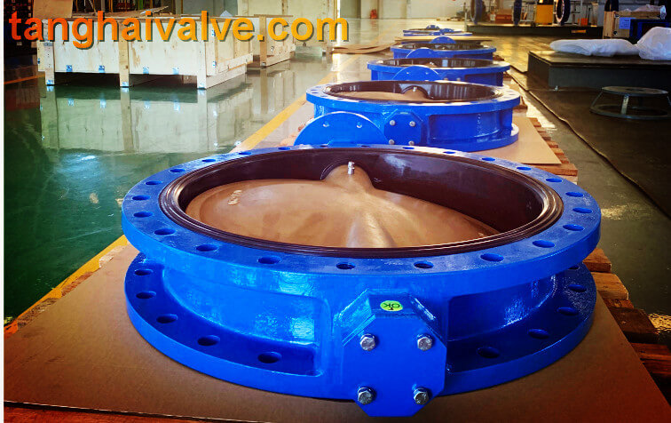
The opening and closing part of the ball valve is a round sphere with a hole. The ball core rotates around the axis of the valve stem by 0-90° back and forth to achieve the purpose of opening or closing the valve. Ball valves have many functions. They are generally used to switch off or adjust the medium in the pipeline. Among them, the three-way ball valve can flexibly cut off, distribute and change the flow direction of the medium. The sealing surface of the ball valve is usually closed with the spherical surface, so it is not easy to be eroded by the medium. It is easy to operate and has a simple and compact structure. It can be used in working conditions such as water, natural gas, acid, and solvent.
fixed ball valve
The application of the ball valve:
Ball valves can generally be divided into three categories: floating ball valves, fixed ball valves, and elastic ball valves according to their structure. According to the different sealing performance, it is divided into hard-sealed ball valves and soft-sealed ball valves. The soft-sealed ball valves have better sealing performance and can achieve zero leakage. They are generally used in normal temperature and pressure pipelines with corrosive media, while hard-sealed ball valves are not only It can be used in normal temperature and pressure, as well as pipelines with low temperature and low pressure and high temperature and high pressure.
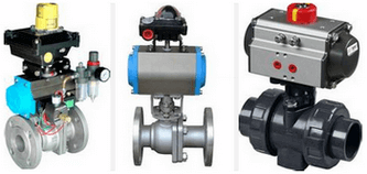
(1) Floating ball valve
The ball of the floating ball valve is floating and is supported by two valve seats. Under the action of the medium pressure, the ball can produce a certain displacement and tightly adhere to the sealing surface of the valve seat at the outlet end to ensure that the outlet end is sealed. However, if the sphere bears the load of the working medium and is all transmitted to the outlet sealing ring, the sphere may deviate when it is impacted by a higher pressure. Therefore, the ball valve of this structure is generally suitable for normal pressure or low pressure working conditions.
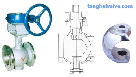
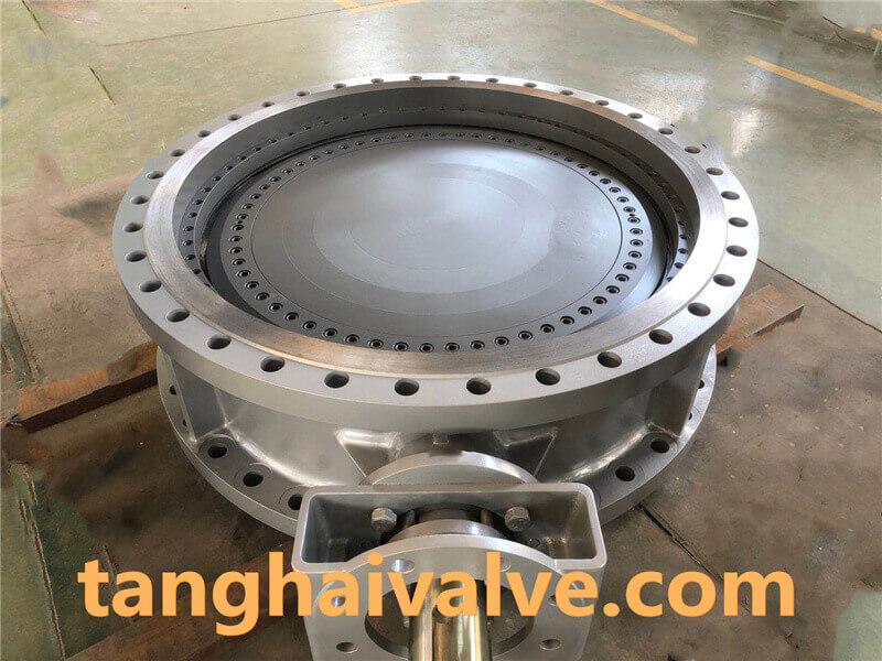
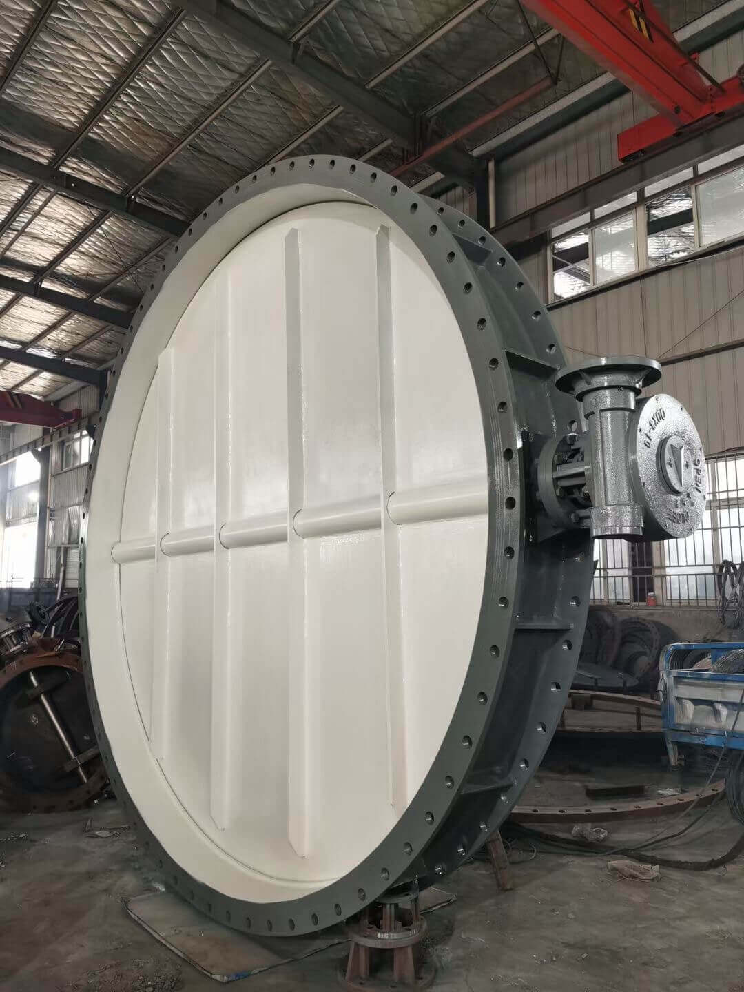
(2) Fixed ball valve
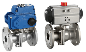
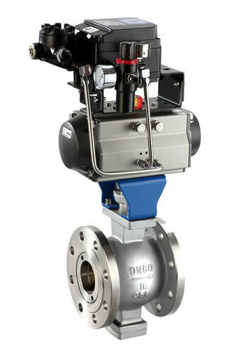
Pneumatic electric high platform ball valve
The name of the fixed ball valve is that the ball is fixed, and when the valve is closed, the ball valve will not move even if it is pressurized. Fixed ball valves are equipped with a floating seat. After being pressured by the medium, the seat will move so that the sealing ring is pressed tightly on the sphere to ensure sealing. Generally, sliding bearings or rolling bearings are installed on the upper and lower shafts of the ball, which can be operated with a small torque and a small torque, and is generally suitable for high-pressure and large-diameter pipelines.
Other common classifications of ball valves, chip ball valves, orbital ball valves, V-shaped ball valves, O-shaped ball valves, cut-off ball valves, three-way ball valves, four-way ball valves, forged steel ball valves, ash unloading ball valves, anti-sulfur ball valves, eccentric ball valves, thermal insulation ball valves, pneumatic Ball valves, electric ball valves, ferrule ball valves, welded ball valves. Among them, the V-shaped ball valve has a shearing effect, which is especially suitable for media containing fibers, small solid particles, slurry and other media. The three-way ball valve can also be divided into T-type and L-type. The T-shape can make the three intersecting pipelines connect to each other or cut off any one of the channels, playing the role of splitting and merging. The L-shape only connects two perpendicular pipes, and cannot connect to the third pipe at the same time, and it mainly plays a role of distribution.
Related knowledge: working principle of ball valve structure diagram of ball valve.
TH Valve is a professional manufacturer of butterfly valve, gate valve, check valve, globe valve, knife gate valve, ball valve with API, JIS, DIN standard, used in Oil, Gas, Marine industry, Water supply and drainage, fire fighting, shipbuilding, water treatment and other systems, with Nominal Diameter of DN50 to DN1200, NBR/EPDM/VITON, Certificates & Approvals: DNV-GL, Lloyds, DNV, BV, API, ABS, CCS. Standards: EN 593, API609, API6D