Main application areas of 10 major types of valves
With the development of society and various needs of modern life, spare parts for the production of these important products are also emerging in endlessly areas. Below we list the main application areas of these 10 categories of

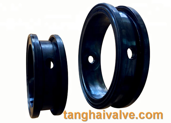
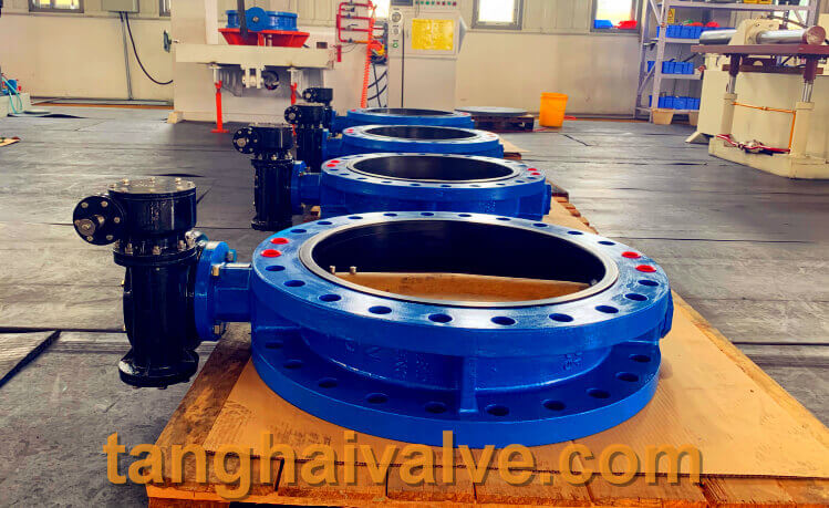
ductile iron, DI, butterfly valve, manufacturer, center line, TH valve
valves.
1. Valves for petroleum installations;
1) Oil refining plant,
Most of the valves used in oil refining equipment are pipeline valves, mainly gate valves, stop valves, check valves, safety valves, ball valves, butterfly valves, and traps. Among them, gate valves account for about 80% of the total number of valves (valves account for about 80% of the total number of valves). 3% to 5% of investment);
2) Chemical fiber device,
Chemical fiber products mainly include polyester, acrylic and vinylon. Ball valves and jacketed valves (jacketed ball valves, jacketed gate valves, jacketed stop valves) of the valves they need;
3) Acrylonitrile device.
The device generally requires standard valves, mainly gate valves, globe valves, check valves, ball valves, traps,
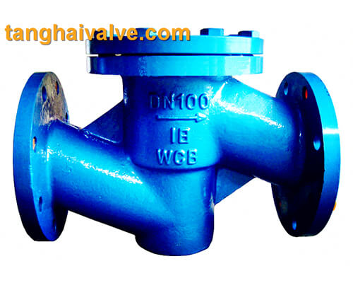
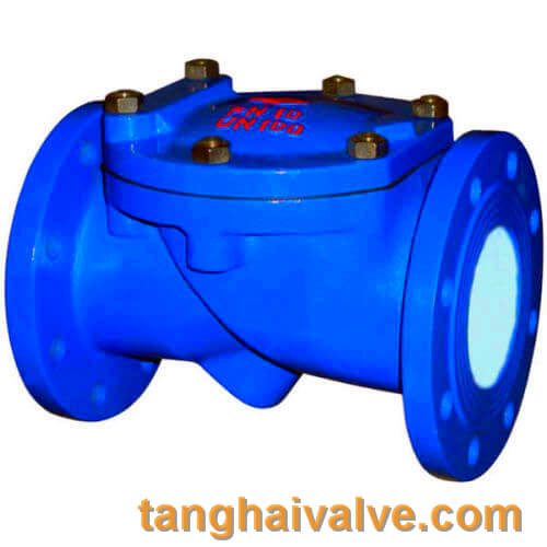
lift-swing-check-valve-2
needle globe valves, and plug valves. Among them, gate valves account for about 75% of the total valve;
4) Synthetic ammonia plant.
Because the ammonia source and purification method are different, the process flow is different, and the technical function of the required valve is also different. At present, domestic ammonia plants mainly need gate valves, globe valves, check valves, traps, butterfly valves, ball valves, diaphragm valves, regulating valves, needle valves, safety valves, high temperature and low temperature valves;
2, Hydropower station application valve
The construction of power stations in my country is developing towards large-scale, so large-caliber and high-pressure safety valves, pressure reducing valves, stop valves, gate valves, butterfly valves, emergency shutoff valves and flow control valves, spherical sealing instrument stop valves are required (according to the country In the “Tenth Five-Year Plan”, in addition to Inner Mongolia and Guizhou provinces, which can build units with more than 200,000 kilowatts, other provinces and cities can only build units with more than 300,000 kilowatts);
3, metallurgical application valve
The behavior of alumina in the metallurgical industry mainly requires wear-resistant slurry valves (in-flow stop valves) and regulating traps. The steelmaking industry mainly needs metal sealed ball valves, butterfly valves and oxidation ball valves, stop flash and four-way reversing valves;
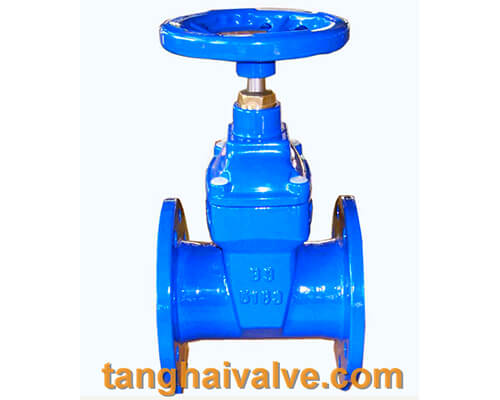
13 gate-valve-5
4, marine application valve
With the development of offshore oilfield exploitation, the amount of valves required for its offshore production has gradually increased. Offshore platforms need to use shut-off ball valves, check valves, and multi-way valves;
5, food and medicine application valve
This industry mainly needs stainless steel ball valves, non-toxic all-plastic ball valves and butterfly valves. Among the above 10 categories of valve products, the demand for general valves is more, such as instrument valves, needle valves, needle globe valves, gate valves, globe valves, check valves, ball valves, and butterfly valves.
6, rural and urban construction application valves
The urban construction department generally uses low-pressure valves, and is currently developing in the direction of environmental protection and energy saving. Environmentally friendly rubber plate valves, balance valves, centerline butterfly valves, and metal seal butterfly valves are gradually replacing low-pressure iron gate valves. Most of the valves used in domestic urban construction are balance valves, soft-seal gate valves, butterfly valves, etc.;
7. Valves for rural and urban heating
In the urban heat generation system, a large number of metal-sealed butterfly valves, horizontal balance valves and direct-buried ball valves are needed, because these valves solve the problem of vertical and horizontal hydraulic imbalance of pipelines, and achieve the purpose of energy saving and heat balance.
8. Environmental protection valve
In the domestic environmental protection system, the water supply system mainly requires centerline butterfly valves, soft-sealed gate valves, ball valves, and exhaust valves (used to remove air in the pipeline). The sewage treatment system mainly needs soft sealing gate valve and butterfly valve;
9. Gas valve
City gas accounts for 22% of the entire natural market, with a large amount of valves and many types. Mainly need ball valve, plug valve, pressure reducing valve, safety valve;
10. Valves for pipeline applications
Long-distance pipelines are mainly crude oil, finished products and natural pipelines. The most commonly used valves for this type of pipeline are forged steel three-body full bore ball valves, anti-sulfur flat gate valves, safety valves, and check valves.
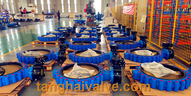
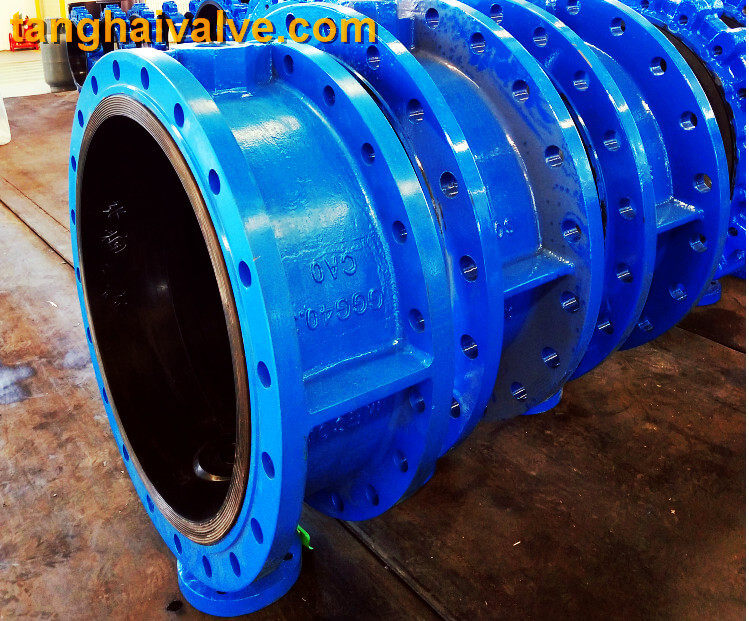
TH Valve is a professional manufacturer of butterfly valve, gate valve, check valve, globe valve, knife gate valve, ball valve with API, JIS, DIN standard, used in Oil, Gas, Marine industry, Water supply and drainage, fire fighting, shipbuilding, water treatment and other systems, with Nominal Diameter of DN50 to DN1200, NBR/EPDM/VITON, Certificates & Approvals: DNV-GL, Lloyds, DNV, BV, API, ABS, CCS. Standards: EN 593, API609, API6D
Related news /knowledge:
The role and classification of valves;
What is a ball valve?
Valve material and valve standards-(8)- Monel alloy application;
Properties of Fixed ball valve