Butt welding of typical workpieces
1, butt welding of small section workpieces
wire with diameter d≤5mm is mostly used for resistance butt welding,
Small diameter wires, wires of different materials, and wires and stamping parts (such as resistors and diode end caps) can be welded by capacitive energy storage type, which is characterized by very hard welding conditions and
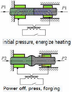
resistance butt welding-Schematic diagram
extremely narrow heating range, which greatly reduces The influence of the thermal and physical properties of the welded metal on the formation of the joint.
2. Butt welding of rods
is mostly used in the butt welding of steel bars in the construction industry, usually resistance butt welding is used for diameter d<10mm; continuous flash butt welding for d>10mm; preheated flash butt welding for d>30mm. When using a manual butt welding machine, because the power of the welding machine is small (usually not more than 50KVA), when d=15-20mm, it is generally necessary to use preheated flash butt welding.
Semi-circular or V-shaped clamp electrodes can be used for butt welding of rods. The latter can be used in various diameters, so it is widely used. The rods are of solid cross-section, with greater rigidity, and longer extension lengths can be used.
3, pipe butt welding
Pipe butt welding is widely used in boiler manufacturing, pipeline engineering and petroleum equipment manufacturing. Choose continuous or preheated flash butt welding according to the section and material of the pipe. The clamp electrode can be semicircular or V-shaped. Usually when the ratio of pipe diameter to wall thickness is greater than 10, a semicircle can be selected to prevent the pipe from being crushed. V-shape can be used when the ratio is less than 10. To prevent the tube from slipping in the clamp electrode, the clamp electrode should have an appropriate working length. When the pipe diameter is 20-50mm, the length of the workpiece is 2-2.5 times the pipe diameter; when the pipe diameter is 200-300mm, it is 1-1.5 times.
Because the tube has an expanded cross-section, the heat dissipation is faster, the liquid metal on the end surface is easy to cool, and it is difficult to extrude during upsetting. The area is scattered, and the self-protection effect is weakened during the flashing process. Therefore, when the process parameters are not selected properly, non-metallic inclusions will remain in the interface to form gray spot defects. Maintain stable flash, increase flash and upsetting speed, and adopt gas protection to reduce or eliminate gray spots.
After the pipe is welded, the internal and external burrs need to be removed to ensure that the external surface of the pipe is smooth and there is a certain channel aperture inside. Deburring requires special tools.
4, thin plate butt welding
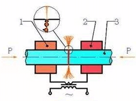
flash butt welding-schematic diagram
Thin plate butt welding is widely used in the continuous production line of rolled steel plate in the metallurgical industry. The width of the plate is from 300 to 1500mm or more, and the thickness is from less than 1mm to more than ten mm. The materials include carbon steel, alloy steel and non-ferrous metals and their alloys. After the plate is butt welded, the joint will undergo rolling and produce great plastic deformation, so it must not only have a certain strength, but also a high plasticity. For steel plates with a thickness of less than 5mm, continuous flash butt welding is generally used, and a plane electrode is used for single-sided conduction. When the plate is thick, preheated flash butt welding is used for double-sided conduction to ensure uniform heating along the entire end surface.
When welding thin plates, due to the relatively large cross-section length and width, the area is scattered, the joint cools quickly, and the self-protection effect is weak during the flashing process. At the same time, the liquid lintel is small and the liquid metal layer on the end surface is thin. Prone to oxidation and solidification. Therefore, the flashing and upsetting speed must be increased. After welding, the burr must be removed with a burr cutting device while it is hot.
5. Butt welding of ring parts
When welding ring parts (such as wheel rims, chain rings, bearing rings, jet engine mounting edges, etc.), in addition to considering the general rules of butt welding process, attention should be paid to the influence of shunting and ring deformation elasticity. Due to the shunt, the required power should be increased by 15-50%. Although the diameter of the ring decreases, the cross section increases, and the material resistivity decreases.
When the ring parts are butt welded, the upsetting pressure must consider the influence of the deformation rebound force, but because the shunt has the effect of heating the ring back, the increase in the upsetting pressure is not large.
Bicycles, motorcycle rims, and automobile rims all use continuous flash butt welding, and the front mouth of the clamp electrode must match the cross-section of the workpiece. During upsetting, in order to prevent the rebound force from affecting the quality of the joint, or even pull the joint apart, it is necessary to extend the time of no current upsetting.
Chain links such as anchor chains and drive chains are mostly used in the manufacture of low-carbon steel and low-alloy steel. Resistance butt welding can be used when diameter d<20mm, and preheating flash butt welding can be used when d>20mm. The purpose of preheating is to heat the interface. Uniform, easy to produce certain plastic deformation during upsetting.
6, tool butt welding
When cutting tool butt welding, one of the current process methods used to manufacture blanks in tool manufacturing is mainly the butt welding of high-speed steel (W8Cr4V, W-9Cr4V2) and medium carbon steel. Tool butt welding has the following characteristics:
1) The thermal conductivity and resistivity of high-speed steel and medium-carbon steel are quite different. At room temperature, medium carbon steel λ=0.42W/(cm℃), ρ0=18-22uΩcm; high-speed steel λ=0.23W/(cm℃), ρ0=48Ωcm. In order to make the temperature distribution on both sides of the joint surface basically the same , The extension length of high speed steel should be 30-50% smaller than that of medium carbon steel. Under normal circumstances, the extension length of high-speed steel is (0.5-1.0)d. In order to prevent excessive heat dissipation, the extension length is not less than 10mm.
2) High-speed steel has a high tendency to quench, the hardness after welding will be greatly increased, and quenching cracks may occur. In order to prevent cracks, preheating flash butt welding can be used. During preheating, heat the metal in the range of 5-10mm near the interface to 1100-1200℃. After welding, it is annealed in an electric furnace at 600-700℃ for 30 minutes.
3) When high-speed steel is heated to a high temperature, it will produce grain growth or the formation of ledeburite eutectic on the semi-melted grain boundary, making the joint brittle. The ledeburite eutectic cannot be eliminated by heat treatment. Therefore, it is necessary to use sufficient upsetting to eliminate this structure.
TH Valve is a professional manufacturer of butterfly valve, gate valve, check valve, globe valve, knife gate valve, ball valve with API, JIS, DIN standard, used in Oil, Gas, Marine industry, Water supply and drainage, fire fighting, shipbuilding, water treatment and other systems, with Nominal Diameter of DN50 to DN1200, NBR/EPDM/VITON, Certificates & Approvals: DNV-GL, Lloyds, DNV, BV, API, ABS, CCS. Standards: EN 593, API609, API6D
Related news/knowledge:
What is butt welding? (1);
What is butt welding? (7)- Flash butt welding of common metals;
What is butt welding? (9)- New technology of flash butt welding;
What is butt welding? (5)- flash butt welding