Characteristics of soft seal /resilient seated gate valves
Title: what are the characteristics of soft seal /resilient seated gate valves?
Traditional gate valves often have water leakage and corrosion. In order to overcome this shortcoming, the soft-seal gate valve appeared. As an updated product of the traditional gate valve, the soft-seal gate valve overcomes the shortcomings of poor sealing performance, poor elasticity, and easy corrosion of general gate valves.
The soft-seal gate valve uses a flexible rubber-wrapped gate, which uses the elastic energy of rubber to produce a small amount of deformation compensation, so that the valve can achieve a good sealing effect. The characteristics of the soft seal gate valve are as follows:
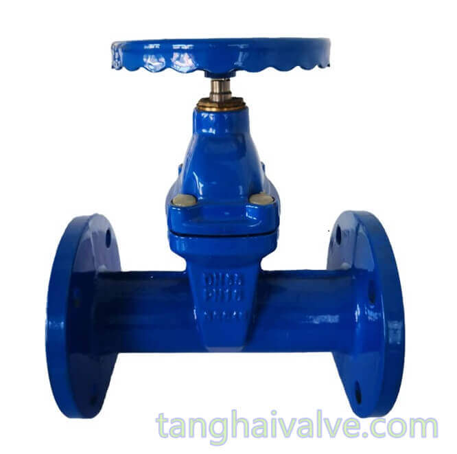
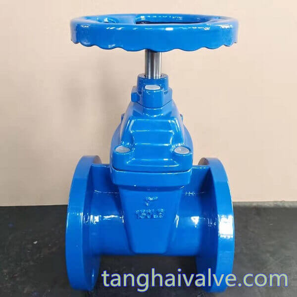
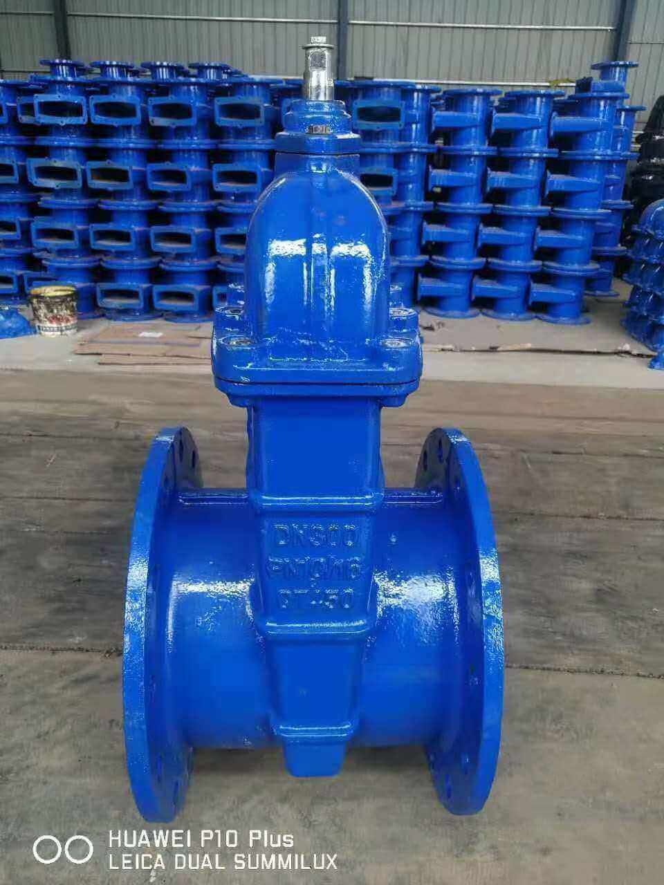
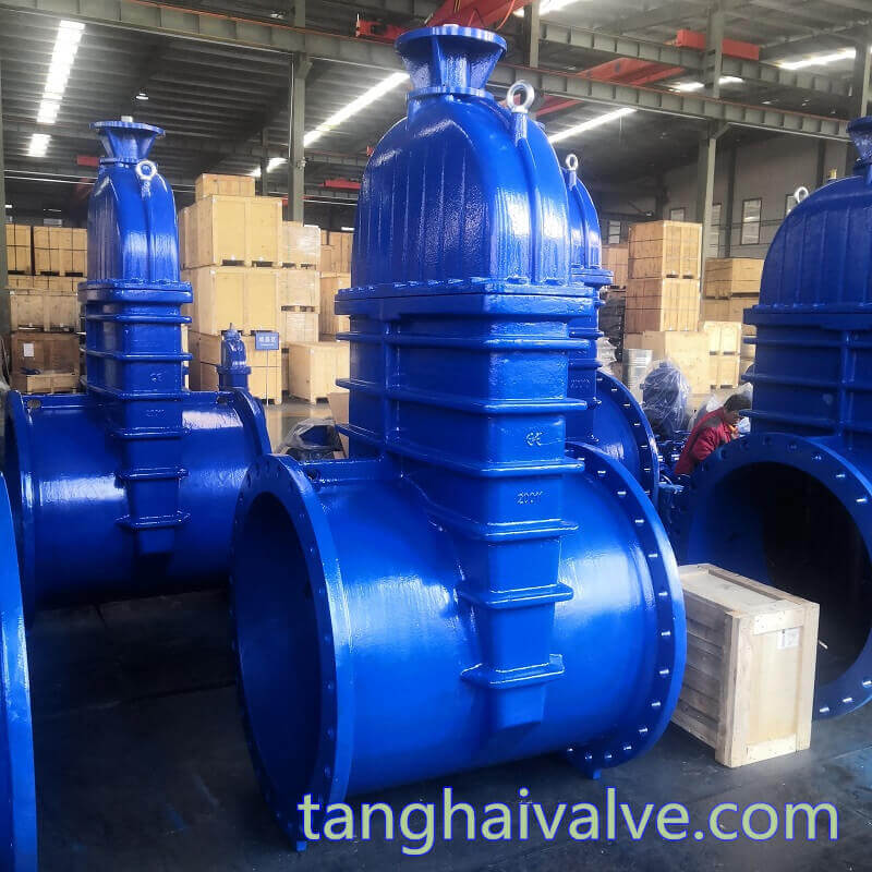
DIN-F5-BB-NRS-soft seated-wedge gate valve (10)
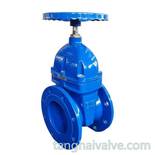
1. The gate is made of integral rubber
Use high-quality rubber to tightly wrap the gate of the soft-seal gate valve as a whole, which improves the sealing performance and is not easy to fall off.
2. The valve body is not easy to rust and corrosion resistant
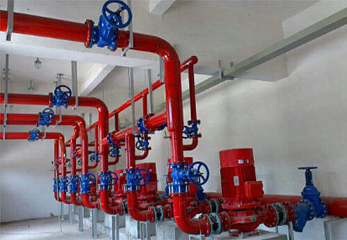
The use of powder epoxy resin to coat the valve body of the soft-seal gate valve can effectively prevent the valve body from being oxidized, not easy to rust, and also prevent the valve body from being corroded. Soft-seal gate valves are often used in sewage treatment systems.
3. The valve seat is designed with a flat bottom
Traditional gate valves usually have a groove at the bottom of the valve seat. When the medium in the pipeline flows through the valve, impurities and particles contained in the medium will settle and silt in the bottom groove, which will make the valve unable to close tightly and cause leakage. Cause an accident. The bottom of the valve seat of the soft sealing gate valve is designed with a flat bottom and has no groove. After the medium in the pipeline flows through, there will be no siltation of impurities and particles, and the sealing performance of the valve is guaranteed to avoid leakage.
4. Precision casting valve body
The valve body of the soft sealing gate valve adopts precision casting, the size is accurate, and the inside of the valve body does not need to do any fine processing, and the sealing performance of the valve body is guaranteed.
5. Ductile iron valve body, light weight
The soft seal gate valve uses ductile iron as the valve body material. The overall weight of the valve is 20%-30% lighter than the traditional gate valve. The lighter weight makes the soft seal gate valve easier to install and maintain.
6. The inside of the valve body is not easy to be corroded
The valve body of the soft sealing gate valve is coated with non-toxic epoxy resin, and the gate is completely wrapped by rubber, which can effectively prevent the inside of the valve body from being corroded by the medium in the pipeline.
7. Three “O” seal ring seal design
The valve stem of the triple “O” seal ring seal design greatly reduces the friction resistance of the soft seal gate valve when it is closed, and the sealing performance is reliable, and no water leakage occurs; the unique design structure also makes the “O” seal ring It can be replaced under pressure and is maintenance-free.
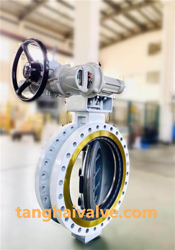
TH Valve is a professional manufacturer of butterfly valve, gate valve, check valve, globe valve, knife gate valve, ball valve with API, JIS, DIN standard, used in Oil, Gas, Marine industry, Water supply and drainage, fire fighting, shipbuilding, water treatment and other systems, with Nominal Diameter of DN50 to DN1200, NBR/EPDM/VITON, Certificates & Approvals: DNV-GL, Lloyds, DNV, BV, API, ABS, CCS. Standards: EN 593, API609, API6D
Related news/knowledge:
Difference between Soft seal gate valve and hard seal gate valve
Difference between soft seal butterfly valve and hard seal butterfly valve
Electric ball valve-metal seated vs soft-seated type
resilient seated butterfly valve vs metal seated butterfly valve