The role of check valve and installation matters
The check valve is an automatic valve that relies on the pressure of the flow of the medium to achieve the opening and closing of the valve flap. The check valve is mainly used to prevent the medium from flowing back and backflow, so it is also called a check valve, a one-way valve and so on. Check valve is a kind of automatic valve, its function is to prevent the back flow of the medium, prevent the pump and drive motor from reversing, as well as the release of the container medium. This article will explain the function of the check valve and the precautions for installation.
The role of the check valve
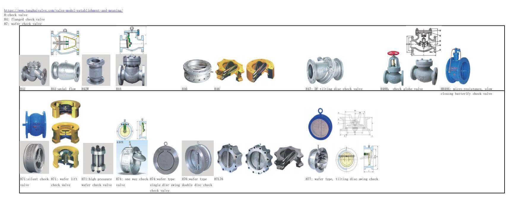
all types of check valve and structures -code names-photos
The check valve is mainly used in the pump water supply system to prevent the impact of the high-pressure water backflow on the pump impeller. When the water pump in the water supply system of the water pump suddenly stops running, the pressure in the pump disappears instantly, and the high-pressure water connected to the outlet of the water pump will flow back to the water pump in the reverse direction. After the non-return valve installed at the outlet of the water pump has no medium pressure, it will be closed immediately to prevent the high-pressure water from flowing back to the pump in the reverse direction.
Imagine if there is no check valve installed at the outlet of the water pump, high-pressure water flows back to the water pump in the reverse direction, and the impeller of the water pump reverses under the impact of the high-pressure water. Under the impact of high-pressure water, the impeller may loosen or damage the impeller or other parts in a serious situation. When the pump runs again, the loose or damaged impeller can also fly out, bringing huge safety hazards to the production work.
The check valve in the hot water system is used to prevent hot water from flowing back into the pipeline. If the check valve is not installed, the hot water will flow back, which may scald the pipeline and even hurt people.
Precautions for check valve installation
1. The check valve is a one-way valve, so the installation position, height, and direction of inlet and outlet must meet the design requirements, and the direction of medium flow should be consistent with the direction of the arrow marked on the valve body.
2. Check the appearance before installing the check valve. The nameplate of the valve should meet the requirements of the current national standard “General Valve Marking” GB 12220. It can be used after all standards are qualified.
3. Do not allow the check valve in the pipeline to bear weight, especially the large check valve, which should have an independent support and not be affected by the pressure generated by the pipeline.
TH Valve is a professional manufacturer of butterfly valve, gate valve, check valve, globe valve, knife gate valve, ball valve with API, JIS, DIN standard, used in Oil, Gas, Marine industry, Water supply and drainage, fire fighting, shipbuilding, water treatment and other systems, with Nominal Diameter of DN50 to DN1200, NBR/EPDM/VITON, Certificates & Approvals: DNV-GL, Lloyds, DNV, BV, API, ABS, CCS. Standards: EN 593, API609, API6D
Related news/knowledge:
What is a single plate check valve;
The role and classification of valves;
The difference between globe valve and check valve;
The role and use of the ball valve