Here we will introduce Rubber variety (abbreviated symbol) with their Chemical composition, Performance characteristics and Main application.
1. Natural rubber (NR) is mainly rubber hydrocarbon (polyisoprene), containing a small amount of protein, moisture, resin acid, sugar and inorganic salt. Large elasticity, high tensile strength, excellent tear resistance and electrical insulation, good wear resistance and drought resistance, good processability, easy to bond with other materials, and superior to most synthetic rubbers in comprehensive performance. Disadvantages are poor resistance to oxygen and ozone, easy to aging and deterioration; poor resistance to oil and solvents, low resistance to acid and alkali, and low heat resistance. Operating temperature range: about -60℃~+80℃. Production of tires, rubber shoes, hoses, tapes, insulation layers and sheaths of wires and cables, and other general products. It is especially suitable for manufacturing torsional vibration eliminators, engine shock absorbers, machine supports, rubber-metal
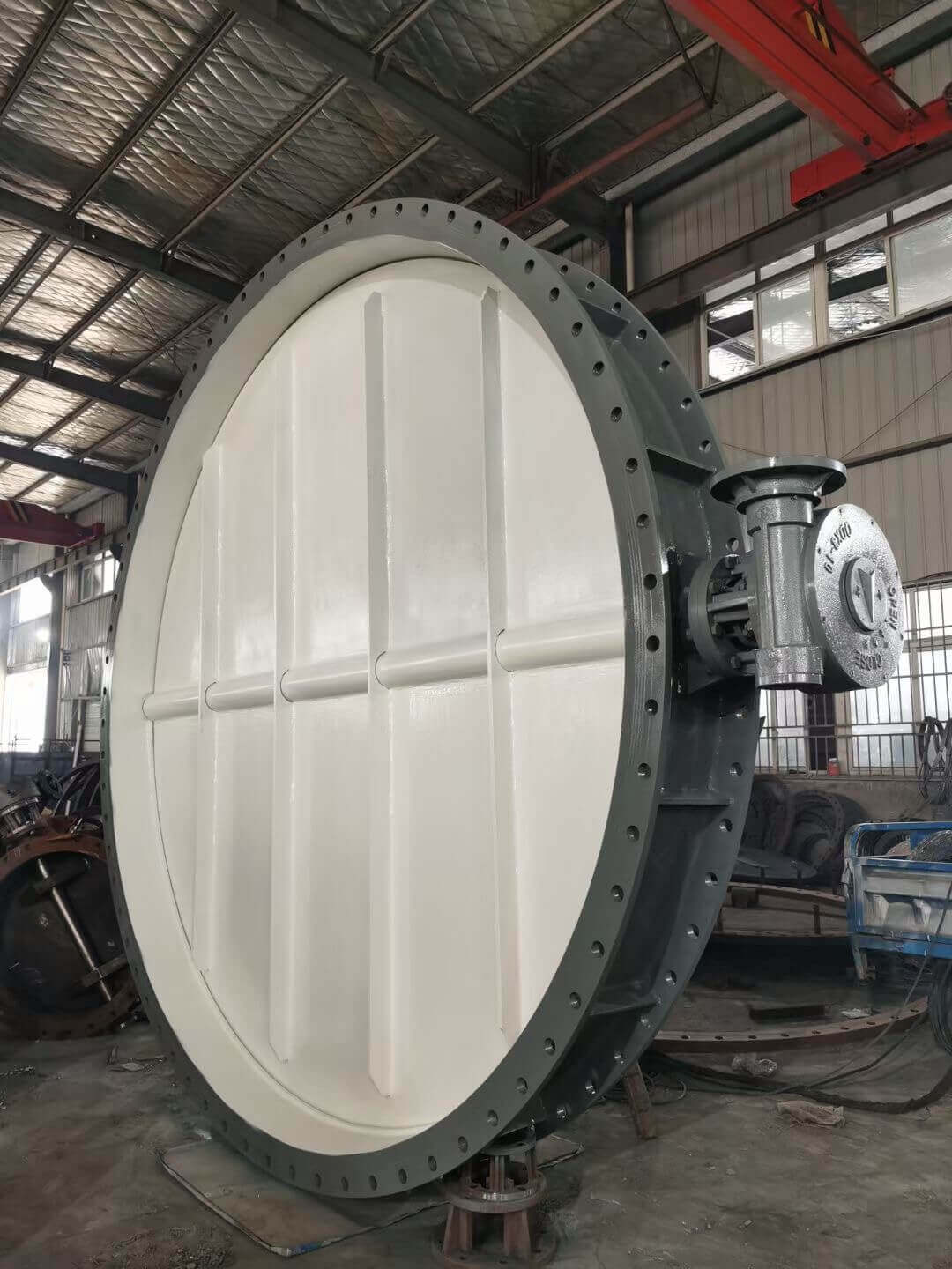
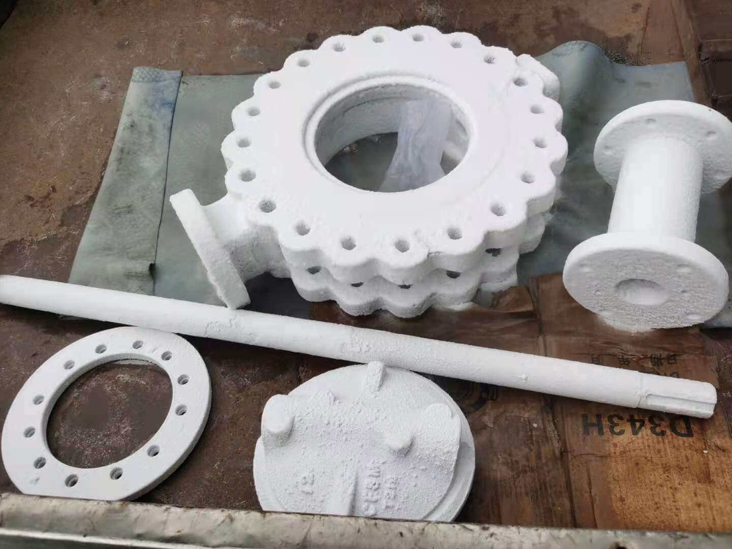
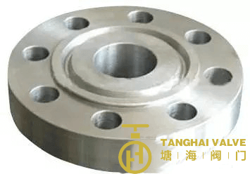
lug type butterfly valve-ductile iron
suspension components, diaphragms, and molded products.
2. Styrene butadiene rubber (SBR) is a copolymer of butadiene and styrene.
The performance is close to natural rubber, and it is currently the largest output of general-purpose synthetic rubber. It is characterized by abrasion resistance, aging resistance and heat resistance exceeding natural rubber, and its texture is more uniform than natural rubber. The disadvantages are: low elasticity, poor flex resistance and tear resistance; poor processing performance, especially poor self-adhesiveness and low green rubber strength. Operating temperature range: about -50℃~+100℃.
Mainly used to replace natural rubber to make tires, rubber sheets, hoses, rubber shoes and other general products.
3. Butadiene rubber (BR)
It is a cis-structure rubber formed by polymerization of butadiene. The advantages are: excellent elasticity and wear resistance, good aging resistance, excellent low temperature resistance, low heat generation under dynamic load, and easy metal bonding. The disadvantages are low strength, poor tear resistance, poor processing performance and self-adhesiveness. Operating temperature range: about -60℃~+100℃.
Generally used together with natural rubber or styrene-butadiene rubber, mainly to make tire treads, conveyor belts and special cold-resistant products.
4. Isoprene rubber (IR) is a kind of cis structure rubber made by polymerization of isoprene monomer. The che
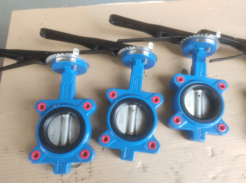
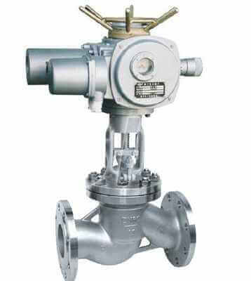
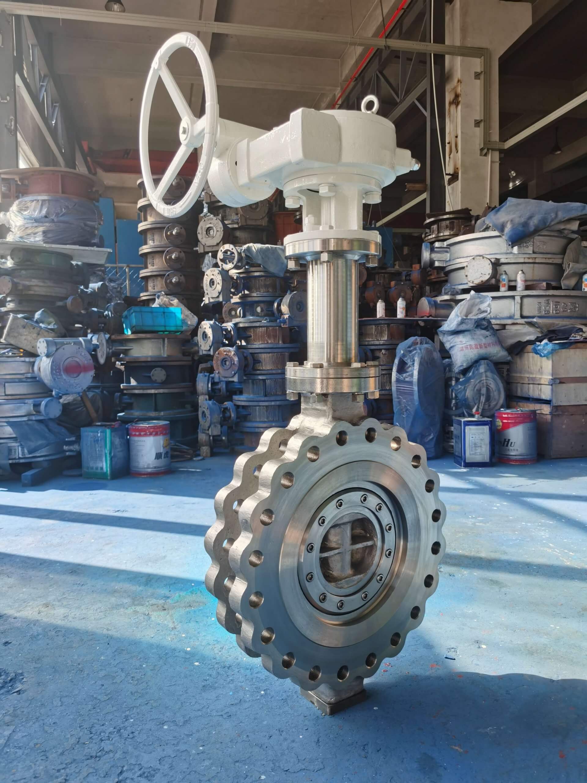
Wafer butterfly valve-PN20-WCB-ANSI-150 (4)
mical composition and three-dimensional structure are similar to natural rubber, and the performance is very close to natural rubber, so it is called synthetic natural rubber. It has most of the advantages of natural rubber. Due to its aging resistance, natural rubber has slightly lower elasticity and strength than natural rubber, poor processing performance and higher cost. Operating temperature range: about -50℃~+100℃ It can replace natural rubber to make tires, rubber shoes, hoses, tapes and other general products.
5. Chloroprene rubber (CR) is a polymer formed by emulsion polymerization of chloroprene as monomer.
This kind of rubber contains chlorine atoms in its molecule, so compared with other general rubbers: it has excellent antioxidant, ozone resistance, non-flammable, self-extinguishing after fire, oil resistance, solvent resistance, acid and alkali resistance, aging and gas resistance. Advantages such as good tightness;
Its physical and mechanical properties are also better than natural rubber, so it can be used as general-purpose rubber as well as special rubber. The main disadvantages are poor cold resistance, large specific gravity, high relative cost, poor electrical insulation, and easy sticking, scorching, and mold sticking during processing. In addition, the raw rubber has poor stability and is not easy to store. Operating temperature range: about -45℃~+100℃. It is mainly used to manufacture cable sheaths and various protective covers and protective covers that require high ozone resistance and high aging resistance; oil and chemical resistance hoses, tapes and chemical linings; flame-resistant rubber products for underground mining, and various moldings Products, sealing rings, gaskets, adhesives, etc.
6. Butyl rubber (IIR) is a copolymer of isobutylene and a small amount of isoprene or butadiene. The biggest feature is good air tightness, good ozone resistance, good aging resistance, high heat resistance, long-term working temperature can be below 130 ℃; resistance to strong inorganic acids (such as sulfuric acid, nitric acid, etc.) and general organic solvents, vibration absorption and damping characteristics Good and very good electrical insulation. The disadvantages are poor elasticity, poor processing performance, slow vulcanization speed, and poor adhesion and oil resistance. Operating temperature range: about -40℃~+120℃. Mainly used as inner tube, water tyre, balloon, wire and cable insulation layer, chemical equipment lining and shockproof products, heat-resistant conveyor belt, heat-resistant aging tape products.
7. Butadiene rubber (NBR) Copolymer of butadiene and acrylonitrile. It is characterized by its excellent resistance to gasoline and aliphatic hydrocarbon oils, second only to polysulfide rubber, acrylic ester and fluorine rubber, but better than other general rubbers. Good heat resistance, good air tightness, abrasion resistance and water resistance, and strong adhesion. The disadvantages are poor cold resistance and ozone resistance, low strength and elasticity, poor acid resistance, poor electrical insulation, and poor resistance to polar solvents. Operating temperature range: about -30℃~+100℃. Mainly used to manufacture various oil-resistant products, such as hoses, sealing products, etc.
8. Hydrogenated butadiene rubber (HNBR) is a copolymer of butadiene and acrylonitrile. It is obtained by fully or partially hydrogenating the double bonds in the butadiene of NBR.
It is characterized by high mechanical strength and abrasion resistance, and its heat resistance is better than NBR when crosslinked with peroxide
Good, other properties are the same as nitrile rubber. The disadvantage is that the price is higher. Operating temperature range: about -30℃~+150℃. Mainly used for oil and high temperature resistant sealing products.
9. Ethylene propylene rubber (EPM\\EPDM)
The copolymer of ethylene and propylene is generally divided into two yuan ethylene propylene rubber and three yuan ethylene propylene rubber.
It is characterized by excellent ozone resistance, ultraviolet resistance, weather resistance and aging resistance, ranking first in general rubber. Electrical insulation, chemical resistance, impact elasticity, acid and alkali resistance, low specific gravity, high filling compounding is possible. Heat resistance up to 150°C, resistance to polar solvents-ketones, esters, etc., but not to aliphatic and aromatic hydrocarbons. Other physical and mechanical properties are slightly inferior to natural rubber and superior to styrene butadiene rubber. The disadvantage is that the self-adhesion and mutual adhesion are very poor, and it is not easy to bond. Operating temperature range: about -50℃~+150℃. Mainly used as chemical equipment lining, wire and cable sheathing, steam hose, heat-resistant conveyor belt, rubber products for automobiles and other industrial products.
10. Silicone rubber (Q)
It is a special rubber with silicon and oxygen atoms in the main chain, of which silicon element plays a major role. Its main feature is high temperature resistance (maximum 300℃) and low temperature resistance (minimum -100℃). It is currently the best high temperature resistant rubber. It has excellent electrical insulation and high stability to thermal oxidation and ozone. , Chemically inert. The disadvantage is that the mechanical strength is low, oil resistance, solvent resistance, acid and alkali resistance are poor, it is difficult to vulcanize, and the price is more expensive. Operating temperature: -60℃~+200℃.
Tanghai Valve is the best manufacturer of butterfly valve, check valve, knife gate valve in China. We produce the best quality products with competitive low prices.
Tianjin Tanghai Valve Manufacturing Co., Ltd. is one of the largest butterfly valve manufacturers in China, main products are butterfly valves, check valves, gate valve and globe valves. Key words: butterfly valve, lug type butterfly valve, wafer type butterfly valve, U-type butterfly valve, double flange butterfly valve, gate valves, check valves, globe valves, valve parts (Valve body, Valve disc, Valve shaft, Valve seat…)
URL: http://www.tanghaivalve.com
Name: Harry Li
Email: harry@tanghaivalve.com