Introduction to the applicable occasions of butterfly valve
Butterfly valve is one of the most commonly used valves in piping systems. It has a wide range of applications. It can not only be used to cut off the flowing medium in the pipeline, but also can be used for flow adjustment. When the fluid in the pipeline passes through the butterfly valve, the pressure loss is about 3 times that of the gate valve, and the pressure loss is relatively large. Therefore, two factors should be considered when choosing a butterfly valve. One is the pressure loss experienced by the piping system, and the other is the pressure of the pipeline medium and the working temperature that the elastic valve seat material can withstand when the butterfly valve is closed.
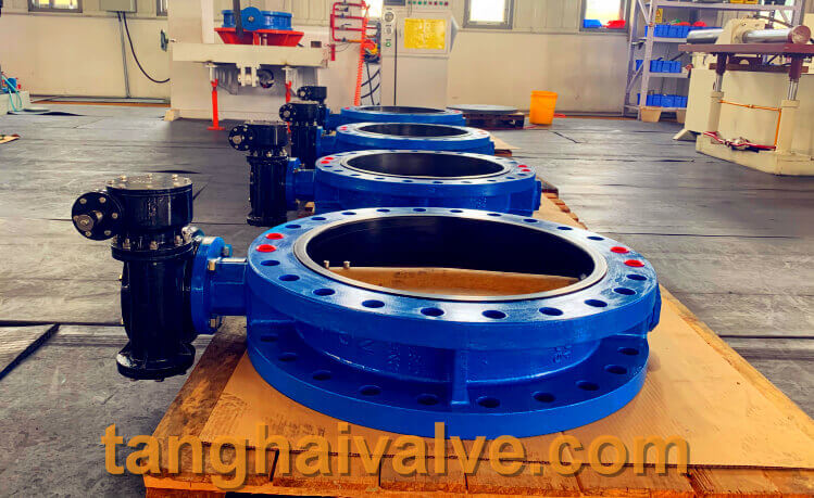
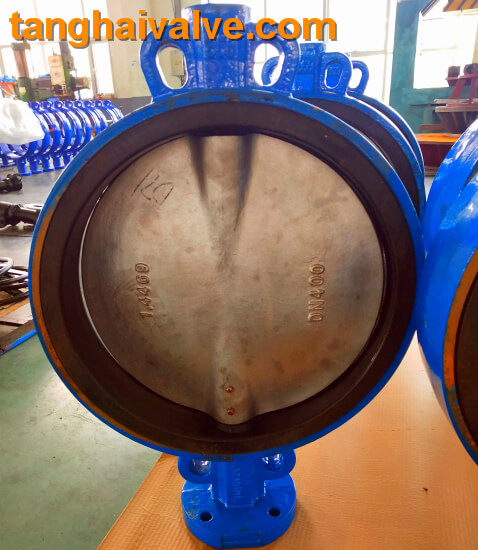
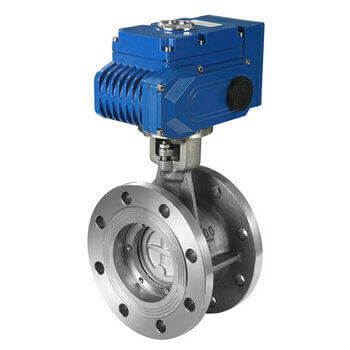
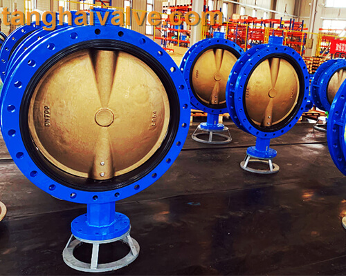
U-type flange butterfly valve, ductile iron, DI, center line,
The structural length of the butterfly valve is short, the overall height is also small, the operating torque is short, it can be opened and closed quickly, and fluid control can be performed well. The structural principle of the butterfly valve makes it most suitable for making large-diameter valves. When the butterfly valve is required to be used for flow control, in order to make it work more effectively, it is necessary to select the correct size and type of the butterfly valve.
What occasions are butterfly valves suitable for?
1. It is required to be used for throttling and regulating control in the pipeline, and the valve structure is required to be short in length and fast in opening and closing. It is recommended to use a butterfly valve.
2. On pipelines that require two-position adjustment and necking, low noise is required, cavitation is generated, a small amount of leakage into the atmosphere, and the circulating medium is corrosive, a butterfly valve can be selected.
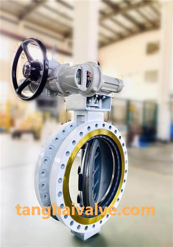
3. Under special working conditions where there are strict requirements for sealing, low temperature containing impurities, and easy to cause wear, it is recommended to use butterfly valves, and to use metal-sealed triple-eccentric or double-eccentric butterfly valves.
4. In the fields of petroleum, petrochemical, chemical, metallurgy, electric power, etc., it is recommended to use metal hard seal triple eccentric butterfly valve. In many cases, it can replace gate valve and stop valve.
5. The center line butterfly valve is suitable for the environment with strict requirements on sealing performance and zero leakage. The center line butterfly valve is most suitable for fresh water, sewage, sea water, salt water, steam, natural gas, oil and oil at a working temperature of -10-150℃. Used in pipelines of various acid and alkali media.
6. The double eccentric butterfly valve is very suitable for use in urban heating, gas, water and gas pipelines, as a device for intercepting or adjusting flow.
7. Eccentric soft sealing butterfly valves are widely used in gas pipelines and waterways in metallurgy, light industry, electric power and petrochemical systems. Used as a two-way opening, closing and adjustment of the ventilation and dust removal pipeline.
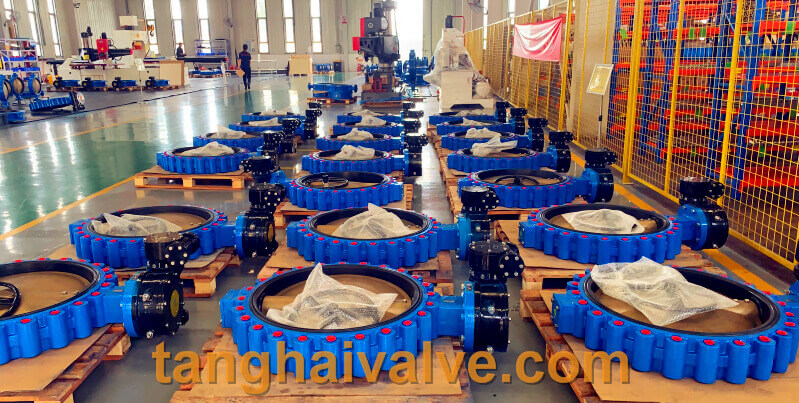
TH Valve is a professional manufacturer of butterfly valve, gate valve, check valve, globe valve, knife gate valve, ball valve with API, JIS, DIN standard, used in Oil, Gas, Marine industry, Water supply and drainage, fire fighting, shipbuilding, water treatment and other systems, with Nominal Diameter of DN50 to DN1200, NBR/EPDM/VITON, Certificates & Approvals: DNV-GL, Lloyds, DNV, BV, API, ABS, CCS. Standards: EN 593, API609, API6D
Related news/knowledge:
Applicable occasions and application conditions of butterfly valves
Applicable occasions and operation method of ball valve
Applicable occasions of butterfly valve
Valve material and valve standards-(8)- Monel alloy application