Working principle and characteristics of triple eccentric butterfly valve
Triple eccentric butterfly valve, also named triple offset butterfly valve.
Nowadays, butterfly valves have been used in many industries. In the beginning, the butterfly valve was only used for the interception and communication of water media. The triple eccentric design enhances the function of the butterfly valve and has become one of the valves with excellent performance in industrial industrial pipeline equipment. The triple eccentric butterfly valve, as the name implies, is that three independent offsets are designed as valves. In reality, many people do not know which one is a triple-eccentric butterfly valve because of insufficient cognition. In this article, let’s talk about the working principle and characteristics of the triple-eccentric butterfly valve.
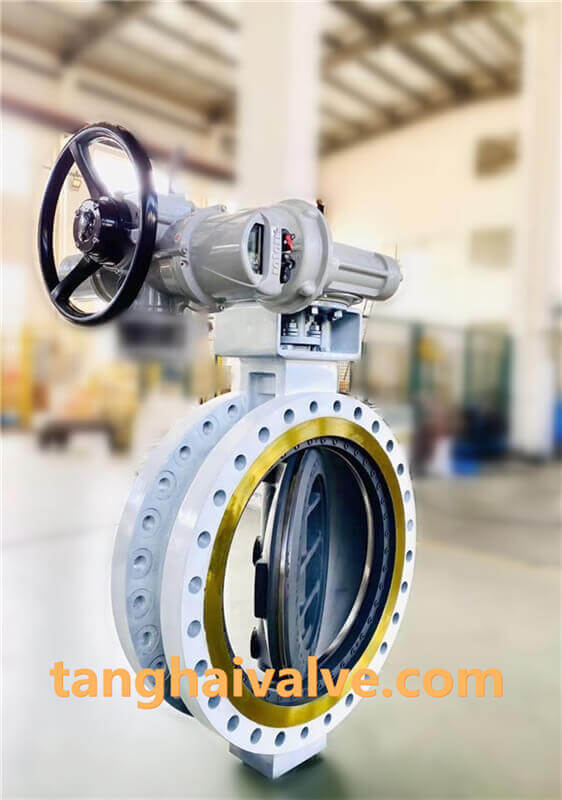
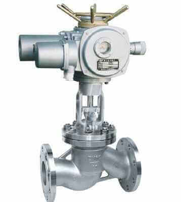
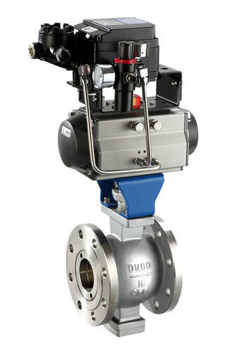
triple offset butterfly valve-double flange- (5)
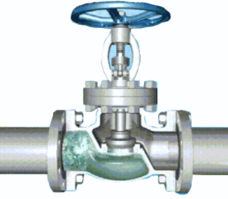
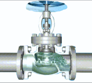
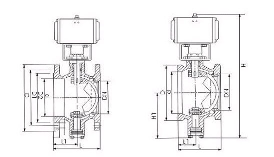
The working principle of the triple eccentric butterfly valve is that the valve body of the butterfly valve has a horizontal valve port connected to the pipeline in structure, and the valve port has a valve plate. The shaft is perpendicular to the valve port and penetrates the valve body and the valve plate. The edge of the valve plate is provided with an outer spherical surface, and the valve port is provided with a sealing surface that can be matched with the outer spherical surface. When the sealing surface and the outer spherical surface are matched and sealed, there is an eccentric distance a between the sealing line and the axis of the shaft, which is in the transverse center of the valve plate. The line is the eccentricity b between the center line of the valve port and the center line of the shaft, and there is an angle β between the connection line of the outer spherical surface and the center line of the valve port. This is the principle of the triple eccentric butterfly valve.
The triple eccentric butterfly valve cleverly puts the triple eccentricity on the valve plate, and adopts a partial outer spherical structure on the outer edge of the valve plate. This structure needs to be completed on a CNC machine with a self-designed simple fixture. The outer eccentric spherical surface is polished to reach a roughness of Ra0.4, the spherical surface is chrome-plated or made of Stellite alloy, and the hardness reaches HRC45-60.
Put the eccentric angle on the valve plate, and press the valve seat on the valve body with a pressing ring, which solves the difficulties encountered in the processing of ordinary triple eccentric butterfly valves. The valve body, valve plate and valve seat cannot be exchanged for pairing. Repair after damage A series of problems such as high cost, all parts are modularized, warehouse management is simple, processing is simple, maintenance is convenient, and the cost of spare parts is reduced.
The butterfly valve is suitable for making large-diameter valves. It can be widely used in the cutting of petroleum transportation pipelines, metallurgical steel plants, gas main pipeline adjustment and cutting, chemical smelting equipment medium adjustment and cutting, water treatment equipment inlet and outlet adjustment and shutdown, and cooling water in thermal power stations. System, natural gas, lye, sea water, acid and other industries.
The characteristics of the triple eccentric butterfly valve are as follows:
1. Simple structure, light weight, composed of only a few parts. easy to use.
2. After the valve plate is fully opened, the thickness of the butterfly plate is the only resistance for the medium to pass through the valve body. The pressure is small and the flow can be better controlled.
3. When the valve plate is closed, the specific pressure between the outer spherical surface of the valve plate and the sealing surface of the valve seat is generated by the driving torque applied to the shaft. Coupled with the elastic compensation of the M-type elastic valve seat, the sealing performance of the valve can be enhanced, and the service life is greatly improved.
Understand the working principle and characteristics of triple eccentric butterfly valve, then where can I buy high-quality triple eccentric butterfly valve products? of course, Tanghai valve.
TH Valve is a professional manufacturer of butterfly valve, gate valve, check valve, globe valve, knife gate valve, ball valve with API, JIS, DIN standard, used in Oil, Gas, Marine industry, Water supply and drainage, fire fighting, shipbuilding, water treatment and other systems, with Nominal Diameter of DN50 to DN1200, NBR/EPDM/VITON, Certificates & Approvals: DNV-GL, Lloyds, DNV, BV, API, ABS, CCS. Standards: EN 593, API609, API6D
Related news/knowledge:
Selection and application of eccentric butterfly valve;
Working principle diagram of three-way valve;
The sealing characteristics and principle of eccentric butterfly valve;