Principle of Globe Valve (Figure)
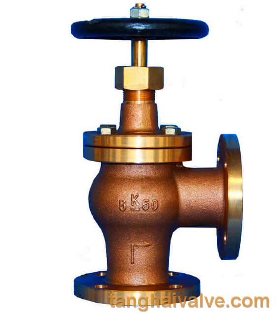
Globe Valve is also called stop valve, shut-off valve. The opening and closing part of the globe valve is a plug-shaped valve disc, the sealing surface is flat or cone, and the valve disc moves linearly along the centerline of the fluid. The movement form of the valve stem includes a lifting rod type (the valve stem is raised and lowered, the hand wheel does not lift), and there is a lifting rotating rod type (the hand wheel and the valve stem rotate and lift together, and the nut is set on the valve body). The stop valve is only suitable for fully open and fully closed, adjustment and throttling are not allowed.
Brief introduction to the principle of the globe valve:
globe cut-off valve working diagram-3D GIF animated presentation
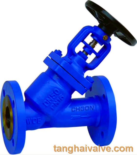
To put it simply, the principle of the globe valve is to use the torsion of the valve stem to give a downward pressure on the sealing surface, and rely on the pressure of the valve stem to make the disc sealing surface and the valve seat sealing surface closely fit to prevent the inflow of the medium or adjust the flow rate of the medium. . The opening and closing part of the stop valve is a cylindrical valve disc, the sealing surface is flat or conical, and the valve disc moves linearly along the center line of the fluid. The movement mode of the valve stem includes a lifting rod type (the valve stem is raised and lowered, and the hand wheel does not lift), and there is also a lifting rotating rod type
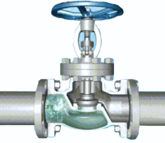
Schematic diagram of shut-off valve (closed state)
(the hand wheel and the valve stem rotate and lift together, and the nut is set on the valve body). The globe valve is a forced sealing valve, so when the valve is closed, pressure must be applied to the disc to force the sealing surface to not leak.
The working principle of the stop valve:
We assume that there is a pipe with a lid. Water flows in from the bottom of the pipe and flows out toward the nozzle. The lid of the outlet pipe is equivalent to the closing part of the shut-off valve. If the pipe lid is lifted up by hand, the water will flow out. When the cap is closed, the water stops flowing, which is equivalent to the working principle of a shut-off valve.
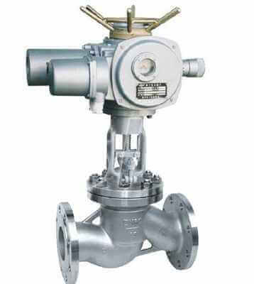
The shut-off valve relies on rotating the hand wheel to make the valve stem rise and fall, and drive the valve disc to make a linear displacement parallel to the flow direction of the medium to achieve the purpose of opening and closing. The handwheel rotates in a clockwise direction, and the working medium enters from the channel under the valve disc. At this time, the applied sealing force must be equal to or greater than the sum of the required specific pressure generated on the sealing surface and the upward force of the medium.
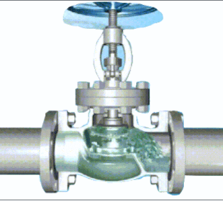
Schematic diagram of shut-off valve (open state)
Schematic diagram of shut-off valve (open state)
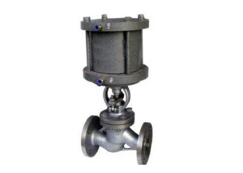
When the shut-off valve is opened, when the opening height of the disc is 25% to 30% of the nominal diameter, the flow has reached the maximum, indicating that the valve has reached the fully open position. Therefore, the fully open position of the shut-off valve should be determined by the stroke of the valve disc.
Note:
1. The shut-off valve only allows the medium to flow in one direction, and has directionality when installed. ,
2. The function of the shut-off valve is either 0 or 1, either through or not through. In other words, the shut-off valve is only suitable for fully open and fully closed, and adjustment and throttling are not recommended.
TH Valve is a professional manufacturer of butterfly valve, gate valve, check valve, globe valve, knife gate valve, ball valve with API, JIS, DIN standard, used in Oil, Gas, Marine industry, Water supply and drainage, fire fighting, shipbuilding, water treatment and other systems, with Nominal Diameter of DN50 to DN1200, NBR/EPDM/VITON, Certificates & Approvals: DNV-GL, Lloyds, DNV, BV, API, ABS, CCS. Standards: EN 593, API609, API6D
Related knowledge:
The working principle and characteristics of the globe valve;
Electric globe valve selection and application;
The working principle of butterfly valve (picture);