Tag Archive for: stop valve

Posts

Comparison table of valve diameter and medium flow rate

It is well known that the flow rate and flow rate of the valve mainly depend on the diameter of the valve, and also
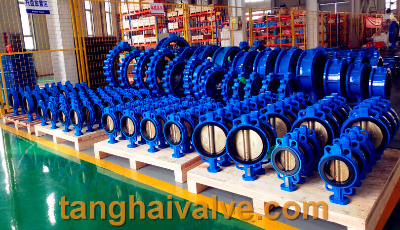
ductile iron, DI, butterfly valve, manufacturer, center line, TH valve

ductile iron, DI, butterfly valve, manufacturer, center line, TH valve

related to the resistance of the valve structure to the medium. At the same time, it has a certain internal connection with various factors such as the valve pressure, temperature and medium concentration. The flow channel area of ​​the valve has a direct relationship with the flow rate and flow rate, and the flow rate and flow rate are two mutually dependent quantities. When the flow rate is constant, the flow rate is large, the flow channel area can be smaller; the flow rate is small, the flow channel area can be larger. On the contrary, the flow channel area is large, its flow velocity is small; the flow channel area is small, its flow velocity is large.
1. The flow rate of the medium is large, and the valve diameter can be smaller, but the resistance loss is large and the valve is easily damaged. If the flow velocity is large, it will have electrostatic effect on flammable and explosive media, causing danger; the flow velocity is too small, the efficiency is low and it is not economical. For the medium with high viscosity and explosive, the flow rate should be smaller. The flow rate of oil and liquid with high viscosity is selected according to the viscosity, generally 0.1~2m/s.
2. In general, the flow rate is known, and the flow rate can be determined by experience. The nominal diameter of the valve can be calculated through the flow rate and flow rate.
3. The valve diameter is the same, its structure type is different, and the fluid resistance is also different. Under the same conditions, the larger the resistance coefficient of the valve, the more the flow rate and flow rate of the fluid through the valve will drop; the smaller the valve resistance coefficient, the less the flow rate and flow rate of the fluid through the valve will drop.
The common flow rates of various media are shown in the following table:

liquid type use condition speed m/s
satuated vapor DN>200 30-40
DN=200-100 25-35
DN<100 15-30
superheated steam DN>200 40-60
DN=200-100 30-50
DN<100 20-40
low pressure steam P<1.0 (absolute pressure) 15-20
midium pressure steam P=1.0-4.0 (absolute pressure) 20-40
high pressure steam P=4.0-12.0 (absolute pressure) 40-60
compressed air vaccum 5-10
P≤0.3 (instrument pressure) 8-12
P=0.3-0.6 (instrument pressure) 10-20
P=0.6-1.0 (instrument pressure) 10-15
P=1.0-2.- (instrument pressure) 8-12
P=2.0-3.0 (instrument pressure) 3-6
P=3.0-30.0 (instrument pressure) 0.5-3
Oxygen P=0-0.05 (instrument pressure) 5-10
P=0.05-0.6 (instrument pressure) 7-8
P=0.6-1.0 (instrument pressure) 4-6
P=1.0-2.0 (instrument pressure) 4-5
P=2.0-3.0 (instrument pressure) 3-4
gas 2.5-15
semi-water gas P=0.1-0.15 (instrument pressure) 10-15
natural gas 30
Nitrogen P=5.0-10.0 (absolute pressure) 15-25
Ammonia vaccum 15-25
P<0.3 (instrument pressure) 8-15
P<0.6 (instrument pressure) 10-20
P≤2 (instrument pressure) 3-8
Acetylene water 30
5-6
Acetylene gas P<0.01 (instrument pressure) 3-4
P<0.15 (instrument pressure) 4-8
P<0.25 (instrument pressure) 5
chlorine  gas 10-25
liquid 1.6
Hydrogen chloride  gas 20
liquid 1.5
liquid ammonia vaccum 0.05-0.3
P≤0.6 (instrument pressure) 0.3-0.8
P≤2.0 (instrument pressure) 0.8-1.5
Sodium hydroxide concentration 0-30% 2
concentration 30-50% 1.5
concentration 50-73% 1.2
Sulfuric acid concentration 88-93% 1.2
concentration 93-100% 1.2
hydrochloric acid 1.5
water and other similar viscosity liquid P=0.1-0.3 (instrument pressure) 0.5-2
P≤1.0 (instrument pressure) 0.5-3
P≤8.0 (instrument pressure) 2-3
P≤20-30 (instrument pressure) 2-3.5
Heating network circulating water Cooling water 0.3-1
pressure backwater 0.5-2
pressureless backwater 0.5-1.2
tap water main pipe P=0.3 (instrument pressure) 1.5-3.5
sub pipe P=0.3 (instrument pressure) 1-1.5
boiler feed water >3
steam condensate 0.5-1.5
condensate free flow 0.2-0.5
superheated water 2
seawater and brackish water P<0.6 (instrument pressure) 1.5-2.5

Note: The unit of DN value is mm; the unit of P value is MPa.
for example:
The resistance coefficient of the gate valve is small, only in the range of 0.1 to 1.5; the resistance coefficient of the large diameter gate valve is 0.2 to 0.5; the resistance coefficient of the narrow gate valve is larger.
The resistance coefficient of the stop valve is much larger than that of the gate valve, generally between 4 and 7.
The resistance coefficient of the Y-type globe valve (DC type) is small, between 1.5 and 2; the resistance coefficient of the forged steel globe valve is large, even as high as 8.
The resistance coefficient of the check valve depends on the structure: the swing check valve is usually about 0.8-2, among which the multi-leaf swing check valve has a large resistance coefficient; the lift check valve has a large resistance coefficient, up to 12 .
The resistance coefficient of the plug valve is small, usually about 0.4 to 1.2.
The resistance coefficient of the diaphragm valve is generally around 2.3.
The drag coefficient of butterfly valve is small, generally within 0.5. The resistance coefficient of the ball valve is small, generally around 0.1.
Note: The resistance coefficient of the above valve is the value when the valve is fully opened. The selection of valve diameter should take into account the machining accuracy and dimensional deviation of the valve, as well as other factors. The valve diameter should have a certain margin, generally 15%. In actual work, the valve diameter depends on the diameter of the process pipeline.

Related products: wafer butterfly valve; lug butterfly valve; double flange butterfly valve;
Double eccentric butterfly valve

TH Valve is a professional manufacturer of butterfly valvegate valvecheck valveglobe valveknife gate valve, ball valve with API, JIS, DIN standard, used in Oil, Gas, Marine industry, Water supply and drainage, fire fighting, shipbuilding, water treatment and other systems, with Nominal Diameter of DN50 to DN1200, NBR/EPDM/VITON, Certificates & Approvals: DNV-GL, Lloyds, DNV, BV, API, ABS, CCS. Standards: EN 593, API609, API6D

Related news/knowledge:
Prevention and treatment of valve corrosion;
Valve flow characteristic curve and classification;
What is the gear modification coefficient;
Valve model establishment and meaning

Description of valve pressure& installation direction requirements

As the name implies, the pressure of the valve refers to the pressure that the valve can withstand, that is, the

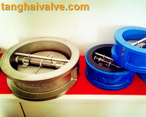
double-wing-check-valve-3

double-wing-check-valve-3

pressure level of the valve is not lower than the design pressure level of the pipeline. The pressure-bearing direction refers to the closed state of the valve after the valve is applied to the pipeline conditions. The arrow direction of the valve body is the recommended pressure-bearing direction. If it is installed incorrectly, the leakage failure of the valve may not be tightly closed. Generally, it is determined according to the use process or usage conditions. The same direction refers to the pressure-bearing direction (the side with high medium pressure on both sides of the valve gate) and the flow direction, and the opposite direction refers to the pressure-bearing direction (both sides of the valve gate) The side with high medium pressure) is opposite to the flow direction of the medium.

Many valves are directional, such as stop valves, throttle valves, pressure reducing valves, check valves, etc. If they are installed upside down, they will affect the use effect and life (such as throttle valves), or they will not work at all (such as Pressure reducing valve), or even cause danger (such as check valve). Normal valves have direction signs on the valve body; if not, they should be correctly identified according to the working principle of the valve.

The arrow marked on the valve body is the recommended pressure direction of the valve, not the flow direction of the pipeline medium. Valves with two-way sealing function may not be marked with an indicating arrow, or with an arrow, because the valve arrow refers to the recommended pressure direction. It is better to have one direction in the left and right or up and down directions. Usually used by the engineering installation company as the medium flow direction to mark the wrong installation, resulting in leakage or even pipeline accidents;

The valve cavity of the shut-off valve is asymmetrical left and right. The fluid must pass through the valve port from bottom to top, so that the fluid resistance is small (determined by the shape), and the opening is labor-saving (because the medium pressure is upward), and the medium does not press the packing after closing, which is convenient for maintenance . This is the reason why the globe valve cannot be reversed. Other valves also have their own characteristics. The location of the valve installation must be convenient for operation; even if the installation is temporarily difficult, it is necessary to consider the long-term work of the operator. It is best to keep the valve handwheel flush with the chest (usually 1.2 meters away from the operating floor), so that it is easier to open and close the valve. The hand wheel of the floor valve should be upward, not tilted, to avoid awkward operation. To

The valve of the wall machine and the equipment should also leave room for the operator to stand. It is necessary to avoid operating from the sky, especially acid and alkali, toxic media, etc., otherwise it is very unsafe. Do not install the gate valve upside down (that is, the handwheel is downward), otherwise the medium will remain in the valve cover space for a long time, which will easily corrode the valve stem, and it is contraindicated by certain process requirements. At the same time, it is extremely inconvenient to replace the packing. The exposed stem gate valve should not be installed underground, otherwise the exposed stem will be corroded due to moisture. When installing the lift check valve, ensure that its valve flap is vertical for flexible lifting. For the swing check valve, ensure that its pin shaft is level during installation to allow flexible swing. The pressure reducing valve should be installed upright on a horizontal pipe, and not inclined in all directions.

TH Valve is a professional manufacturer of butterfly valvegate valvecheck valveglobe valveknife gate valve, ball valve with API, JIS, DIN standard, used in Oil, Gas, Marine industry, Water supply and drainage, fire fighting, shipbuilding, water treatment and other systems, with Nominal Diameter of DN50 to DN1200, NBR/EPDM/VITON, Certificates & Approvals: DNV-GL, Lloyds, DNV, BV, API, ABS, CCS. Standards: EN 593, API609, API6D

Related news /knowledge:
Working principle diagram of swing check valve;
Installation instructions of double eccentric butterfly valve;
Butterfly valve use principle and installation instructions;
Butterfly valve and its Development history – (1)

Electric globe valves’ structural features and installation attention

Structural features of electric globe valve:

1. Open and close without friction. This function completely solves the problem of traditional valves affecting the

Globe valve (6)

Globe valve (6)

sealing due to mutual friction between the sealing surfaces.

2. Top-mounted structure. The valves installed on the pipeline can be directly inspected and repaired online, which can effectively reduce device shutdown and reduce costs.

3. Single valve seat design. Eliminates the problem that the medium in the valve cavity affects the safety of use due to abnormal pressure increase.

4. Low torque design. The valve stem with special structure design can be opened and closed easily with only a small handle.

5. Wedge-shaped sealing structure. The valve relies on the mechanical force provided by the valve stem to press the ball wedge onto the valve seat to seal, so that the sealing performance of the valve is not affected by changes in pipeline pressure, and the sealing performance is reliably guaranteed under various working conditions.

6. Self-cleaning structure of the sealing surface. When the ball is tilted away from the valve seat, the fluid in the pipeline passes through the sealing surface of the ball evenly at 360°, which not only eliminates the local erosion of the valve seat by the high-speed fluid, but also washes away the accumulation on the sealing surface to achieve the purpose of self-cleaning .

7. The valve body and bonnet with valve diameter below DN50 are die forgings, and the valve body and bonnet above DN65 are steel castings.

8. The connection forms of the valve body and the bonnet are different, clamp pin shaft connection, flange gasket connection and self-sealing thread connection.

9. The sealing surfaces of the valve seat and the valve disc are all made of plasma spray welding or surfacing welding of cobalt-chromium-tungsten cemented carbide. The sealing surface has high hardness, wear resistance, scratch resistance and long service life.

10. The valve stem material is nitrided steel. After nitriding, the surface of the stem has high hardness, wear resistance, scratch resistance, corrosion resistance and long service life.

Electric shut-off valve installation attention:

1. Pay attention to the flow direction of the medium when installing the valve, and install it strictly in the direction indicated by the valve flow direction arrow.

2. The valve can be installed at any position of the pipeline, and at the same time, choose a carbon steel or alloy steel valve according to the temperature of the medium and the medium.

3. The electric globe valve should be installed vertically as far as possible, with the valve stem upward.

TH Valve is a professional manufacturer of butterfly valvegate valvecheck valveglobe valveknife gate valve, ball valve with API, JIS, DIN standard, used in Oil, Gas, Marine industry, Water supply and drainage, fire fighting, shipbuilding, water treatment and other systems, with Nominal Diameter of DN50 to DN1200, NBR/EPDM/VITON, Certificates & Approvals: DNV-GL, Lloyds, DNV, BV, API, ABS, CCS. Standards: EN 593, API609, API6D

Related news /knowledge:
Installation attentions for valves;
Structural characteristics of butterfly valve
Structural characteristics of metal hard seal butterfly valve;
The structural characteristics and uses of the wafer butterfly valve;

Characteristics and working principle of electric globe valve

Features of electric globe valve:

  • The fluid resistance is small, and its resistance coefficient is equal to that of a pipe section of the same length.

    Globe valve (9)

    Globe valve (9)

  • Simple structure, small size and light weight. Electric globe valve
  • It is tight and reliable. The sealing surface material of the gate valve is widely used plastic, and it has good sealing performance. It has also been widely used in vacuum systems.
  • It is easy to operate and open and close quickly. It only needs to rotate 90° from fully open to fully closed, which is convenient for remote control.
  • The maintenance is convenient, the gate valve has a simple structure, the sealing ring is generally movable, and it is convenient to disassemble and replace.
  • When fully open or fully closed, the sealing surface of the ball and the valve seat is isolated from the medium, and the medium will not cause erosion of the valve sealing surface when the medium passes.
  • It has a wide range of applications, with a diameter ranging from a few millimeters to a few meters, and can be applied from high vacuum to high pressure.

Electric globe valve classification:

According to its channel position, it can be divided into straight-through type and right-angle type.

Working principle of electric globe valve:

The working principle of the electric shut-off valve is to make the valve unblocked or blocked by rotating the valve. The gate valve switch is light, small in size, can be made into a large diameter, reliable in sealing, simple in structure, convenient in maintenance, the sealing surface and the spherical surface are often closed, and it is not easy to be eroded by the medium. It is widely used in various industries.

A. Opening process of globe check valve:

  • In the closed position, the valve body is pressed against the valve seat by the mechanical pressure of the valve stem.
  • When the hand wheel is turned counterclockwise, the valve stem moves in the opposite direction, and the angular plane at the bottom causes the ball to separate from the valve seat.
  • The valve stem continues to lift and interacts with the guide pin in the spiral groove of the valve stem, so that the ball begins to rotate without friction.
  • Until it reaches the fully open position, the valve stem is raised to the limit position, and the ball rotates to the fully open position.

B. Closing process of electric globe valve:

  • When closing, turn the handwheel clockwise, the valve stem begins to drop and the ball leaves the valve seat to start rotating.
  • Continue to rotate the hand wheel, and the valve stem will be acted on by the guide pin embedded in the upper spiral groove to make the valve stem and the gate rotate 90° at the same time.
  • When it is about to close, the gate body has rotated 90° without contact with the valve seat.
  • In the last few turns of the handwheel, the angular plane at the bottom of the valve stem mechanically wedges and presses the sphere to make it tightly press on the valve seat to achieve a complete seal.

TH Valve is a professional manufacturer of butterfly valvegate valvecheck valveglobe valveknife gate valve, ball valve with API, JIS, DIN standard, used in Oil, Gas, Marine industry, Water supply and drainage, fire fighting, shipbuilding, water treatment and other systems, with Nominal Diameter of DN50 to DN1200, NBR/EPDM/VITON, Certificates & Approvals: DNV-GL, Lloyds, DNV, BV, API, ABS, CCS. Standards: EN 593, API609, API6D

Related news/knowledge:
Characteristics of ball valve;
The working principle of butterfly valve (picture);
Electric ball valve principle | Electric ball valve working principle;
Working principle of electric gate valve

Comparison of bellows globe valve and ordinary globe valve

Comparison of bellows globe valve and ordinary globe valve:

Globe valve (3)

Globe valve (3)

1. Double sealing design (bellows + packing) If the bellows fails, the stem packing will also avoid leakage and meet international sealing standards.
2. There is no fluid loss, reducing energy loss and improving plant equipment safety.
3. Long service life, reduce maintenance times and lower operating costs.
4. The sturdy and durable bellows seal design ensures zero leakage of the valve stem and provides maintenance-free conditions.
5. The gas medium valve seat adopts PTFE soft sealing material to improve the sealing performance of this valve.
6. High temperature resistance≤425℃The valve seat adopts conical hard seal. Achieve airtight performance and zero leakage.

Tianjin Tanghai Valve Manufacturing Co., Ltd. is one of the largest globe valve manufacturers in China, main products are butterfly valves, check valves, gate valves and globe valves. Key words: butterfly valve, lug type butterfly valve, wafer type butterfly valve, U-type butterfly valve, double flange butterfly valve, gate valves, check valves, globe valves, valve parts (Valve body, Valve disc, Valve shaft, Valve seat…)

Our products use advanced manufacturing technology, and strictly conform to API, DIN, BS, EN, ISO, GB and other international standards. The main products are butterfly valves, gate valves, check valves, globe valves, valve parts (Valve body, Valve disc, Valve shaft, Valve seat…), etc. Our products are widely used in various fields such as marine industry, shipbuilding, petrochemical, metallurgy, water treatment, fire fighting, water supply and drainage, etc. The company has won unanimous recognition and praise from customers with high quality and good reputation.

Classification of the globe valves-(2)

According to the classification of purposes, the globe valve can be divided into the following types:

12 Globe-valve-4

12 Globe-valve-4

The fluorine-lined stop valve: it is suitable for various concentrations of aqua regia, sulfuric acid, hydrochloric acid, hydrofluoric acid and various organic acids, strong acids, strong oxidants, and various concentrations of strong alkali organic solvents and other Use on corrosive gas and liquid medium pipelines.

The national standard globe valve: it is the most commonly used product in the globe valve series. The API American standard globe valve and the American standard globe valve implement ANSI and API standards. The sealing surfaces of the disc and seat are made of Stellite cobalt-based hard with different hardness. It is made of alloy surfacing, with reliable sealing, high hardness, wear resistance, high temperature resistance, corrosion resistance, good scratch resistance and long life.

Needle valve: it is a small-caliber instrument valve, which plays a role of opening and closing and precise flow control in the instrument measurement pipeline system. It mainly includes power station instrument series, oil field special series, American standard series, etc.

Cryogenic globe valve: it usually refers to the valve whose working temperature is lower than -110℃, which is widely used in LNG, LPG and other low temperature industries. Since 2008, the globe valve with a suitable temperature of -196℃ can be manufactured, and all parts are pretreated with liquid nitrogen at low temperature to completely avoid seal deformation and leakage during use.

The plunger valve: it is also known as the plunger stop valve. Its sealing surface adopts a radial sealing structure. The load exerted on the valve cover by two elastic sealing rings sleeved on the polished plunger through the connecting bolts of the valve body and the valve cover The elastic sealing ring around the plug compresses the shut-off valve for sealing.

The insulation jacket cut-off valve: it adopts the insulation jacket design, using external heat source to circulate heating outside the valve, which can effectively prevent temperature loss when the medium passes through the valve and ensure the temperature of the medium.

The forged steel globe valve: it is designed and manufactured in accordance with API 602 standards, and provides three bonnet design forms: bolted bonnet, welded bonnet, pressure self-tightening bonnet, users can choose different forms according to their needs, providing RF flanges, NPT thread, SW welding type three connection methods.

The special oxygen stop valve: it is made of silicon brass or stainless steel with excellent material, which has the advantages of high mechanical strength, wear resistance, and good safety. Used in oxygen pipelines, it has the best explosion-proof and flame-retardant performance, eliminates the unsafe factors on the oxygen pipelines, and is widely used in the pipeline network of oxygen-using projects such as steel, metallurgy, petrochemical, and chemical industries. In addition to the functions of ordinary valves, it also has its own characteristics. Strict oil prohibition measures are adopted during manufacturing, and all parts are subjected to strict degreasing treatment before installation.

The bellows stop valve: it adopts a shaped stainless steel bellows design. The bellows reciprocating test is 10,000 times without failure, and the sealing performance is reliable. It is suitable for industrial and mining with inflammable, explosive, toxic and harmful media, and can effectively prevent valve leakage.

Tianjin Tanghai Valve Manufacturing Co., Ltd. is one of the largest  valve manufacturers in China, main products are butterfly valves, check valves, gate valve and globe valves. Details: butterfly valve, lug type butterfly valve, wafer type butterfly valve, U-type butterfly valve, double flange butterfly valve, gate valves, check valves, globe valves, valve parts (Valve body, Valve disc, Valve shaft, Valve seat…)

Classification of the globe valves-(1)

According to the channel direction, the globe valve is devided into 4 types:

Globe valve (6)

Globe valve (6)

1) Straight-through globe valve.
2) Direct flow stop valve: In direct flow or Y-shaped stop valve, the flow passage of the valve body is in a diagonal line with the main flow passage, so that the damage degree of the flow state is less than that of the conventional stop valve, so the pressure loss through the valve is also corresponding Is too small.
3) Angle type stop valve: In the angle type stop valve, the fluid only needs to change its direction once, so that the pressure drop through this valve is smaller than that of the conventional structure.
4) Plunger type globe valve: This type of globe valve is a variation of the conventional globe valve. In this valve, the disc and valve seat are usually designed based on the plunger principle. The valve clack is polished so that the plunger is connected to the valve stem, and the sealing is achieved by two elastic sealing rings sleeved on the plunger. The two elastic sealing rings are separated by a collar, and the sealing ring around the plunger is pressed firmly by the load exerted on the bonnet by the bonnet nut. The elastic sealing ring can be replaced and can be made of various materials. The valve is mainly used for “open” or “close”, but it is equipped with a special form of plunger or a special collar, which can also be used to adjust the flow .

The position of the thread on the valve stem:

1) Upper threaded stem stop valve: The thread of the stem of the stop valve is on the outside of the valve body. The advantage is that the valve stem is not corroded by the medium and is convenient for lubrication. This structure is more common.

2) Bottom thread stem stop valve: The thread of the stem of the stop valve is in the valve body. The stem thread of this structure is in direct contact with the medium, which is susceptible to corrosion and cannot be lubricated. This structure is used in places with small diameters and low temperatures.

There are many domestic manufacturers of globe valves, and most of the connection sizes are not uniform. It is mainly divided into the following categories: General category based on JB/T2203-1999 “Structural Length of Stop Valves”. At present, most domestic shut-off valve manufacturers design and produce according to this standard. However, this standard is not perfect, and the specifications are not complete. The maximum nominal diameter of a single gate valve is DN1200, and the maximum nominal diameter of a double gate valve is DN1500. According to the specifications of the shut-off valve produced by the manufacturer and the information available, the smallest nominal diameter of the angle-type shut-off valve is DN15, and the nominal diameter of the Z-type straight-through shut-off valve reaches DN2000. After research, the connection size of each manufacturer is not uniform. In order to have a unified standard, users can interchange the same specifications when selecting and installing, it is recommended that China General Machinery Research Institute revise JB/T2203-1999 “Structural Length of Stop Valves”. It is recommended that the design institute and users choose according to the standard, and the stop valve manufacturer should design and manufacture according to the standard.