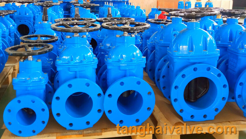
Non-rising stem(NRS) and rising stem(RS) gate valve
structures and differences of Non-rising stem(NRS) gate valve and rising stem(RS) gate valve
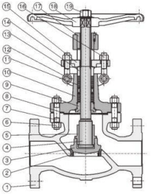
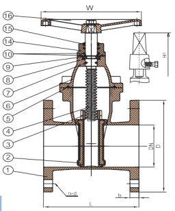
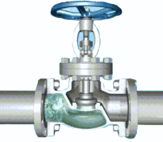
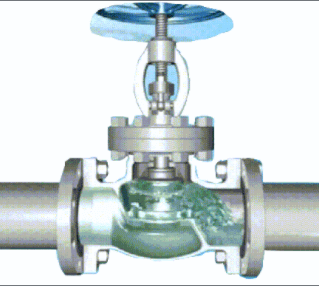
RS gate valve structure picture, NRS gate valve structure picture
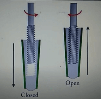
non-rising stem gate valve-open and close position
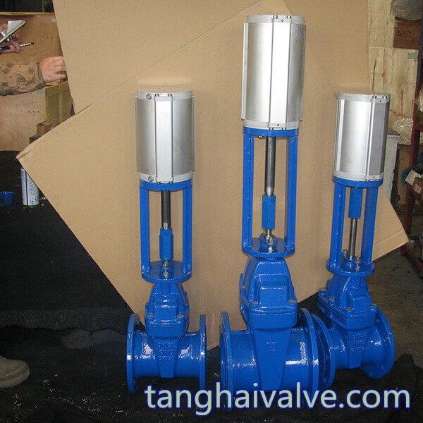
RS gate valve and NRS gate valve are different from the transmission mode. RS gate valve is a handwheel that drives a nut to rotate in place, and the stem is linearly raised and lowered to complete the switch; NRS gate valve is a handwheel that drives the stem to rotate, and there are threads in the gate. Nut) to move up and down to complete
the switch.
Structural principle of gate valve:
1. NRS gate valve structure: The stem nut is in the valve body and is in direct contact with the medium. When opening and closing the gate, it is realized by rotating the valve stem.
2. RS gate valve structure: the stem nut is on the bonnet or bracket. When opening and closing the gate, the stem nut is rotated to realize the lifting of the stem.
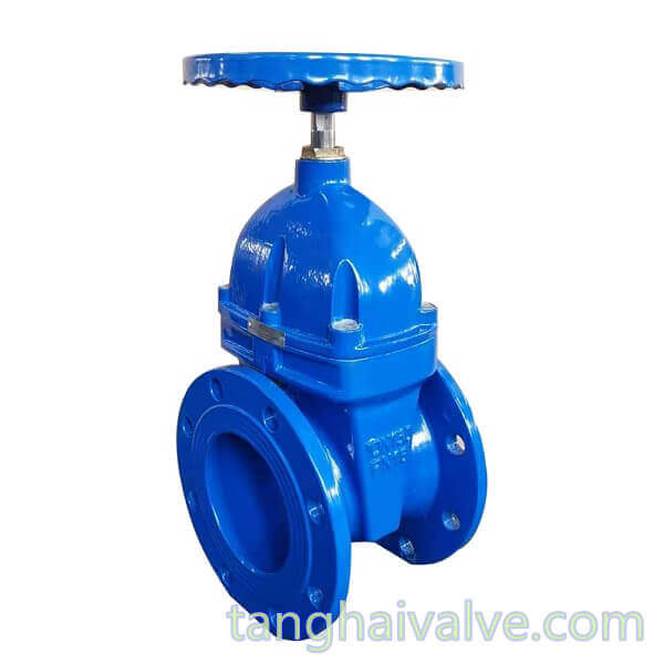
DIN-F4-BB-NRS-soft seated-wedge gate valve-DN100-PN16-copper holding ring-handwheel (3)
The difference between RS gate valve and NRS gate valve:
1. RS gate valve can see the screw, but NRS can not see the screw;
2. The RS gate valve raises or lowers the disc through the threaded transmission of the valve stem and the steering wheel; when the NRS gate valve is switched on and off, the steering wheel and the valve stem are connected and relatively immobile. It drives the valve through the rotation of the valve stem at a fixed point. The flap is lifted up and down to complete the opening and closing;
3. The transmission thread of the NRS gate valve is located inside the valve body. During the opening and closing process, the valve stem only rotates, and the gate is raised and lowered in the valve body; the valve stem of the RS gate valve drives the gate to rise and fall together, and the drive thread on the valve stem Outside the valve body, the opening and closing and position of the gate can be intuitively judged according to the movement direction and position of the valve stem;
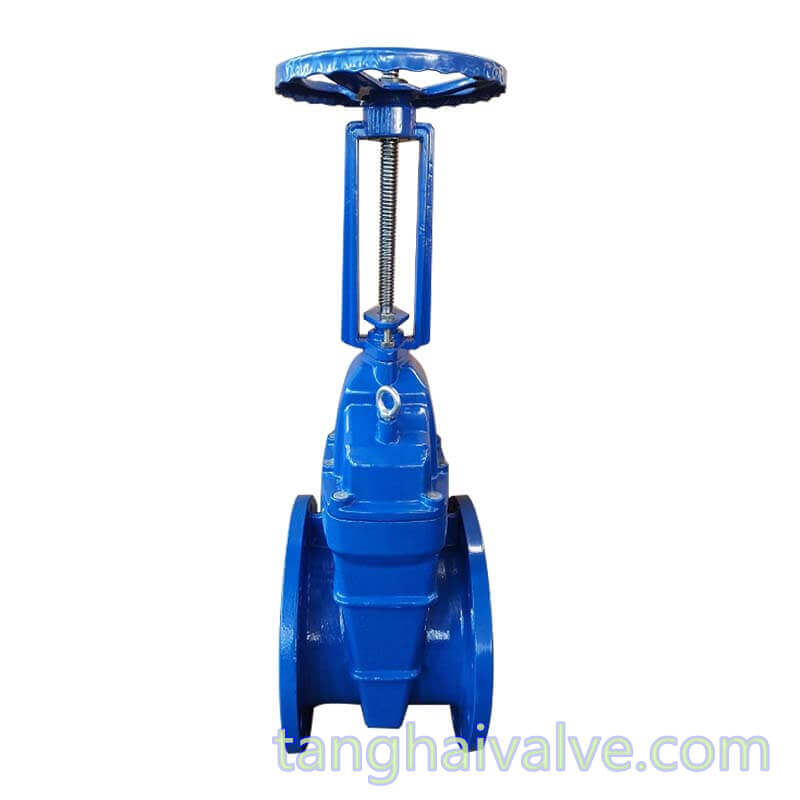
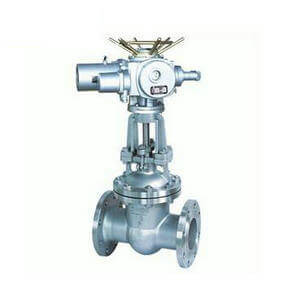
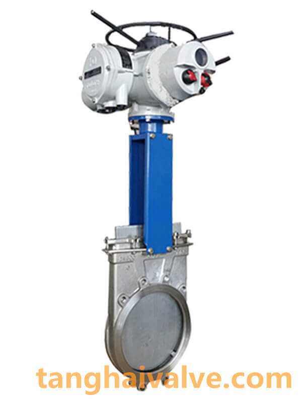
rising stem gate valve-RS-BB OS&Y (3)
4. The height of the NRS gate valve is small; the RS gate valve requires a larger installation space;
5. The structure of the RS gate valve is beneficial to the lubrication of the valve stem, and the degree of opening and closing is obvious; the thread of the valve stem of the NRS gate valve is not only unable to be lubricated, but it is directly corroded by the medium and is easily damaged. Therefore, the RS gate valve is more widely used.
Related news /knowledge:
structures and differences of Non-rising stem(NRS) and rising stem(RS) gate valve;
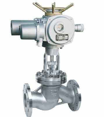
Characteristics and working principle of electric globe valve;
The working principle of butterfly valve (picture);
How many types of gate valves?;