Article title: Application of low temperature triple eccentric butterfly valve
With the rapid development of industrial technology, more stringent requirements have been put forward for valves, especially for butterfly valves used in low temperature media. In addition to meeting the performance of general valves, it is more important that butterfly valves seal under low temperature conditions. Reliability, flexibility of action and some other special requirements for cryogenic valves. Now combined with its structural characteristics, a brief introduction to the performance of the cryogenic butterfly valve is given. Remarks: The cryogenic butterfly valve we are talking about here specifically refers to the low temperature triple eccentric butterfly valve.
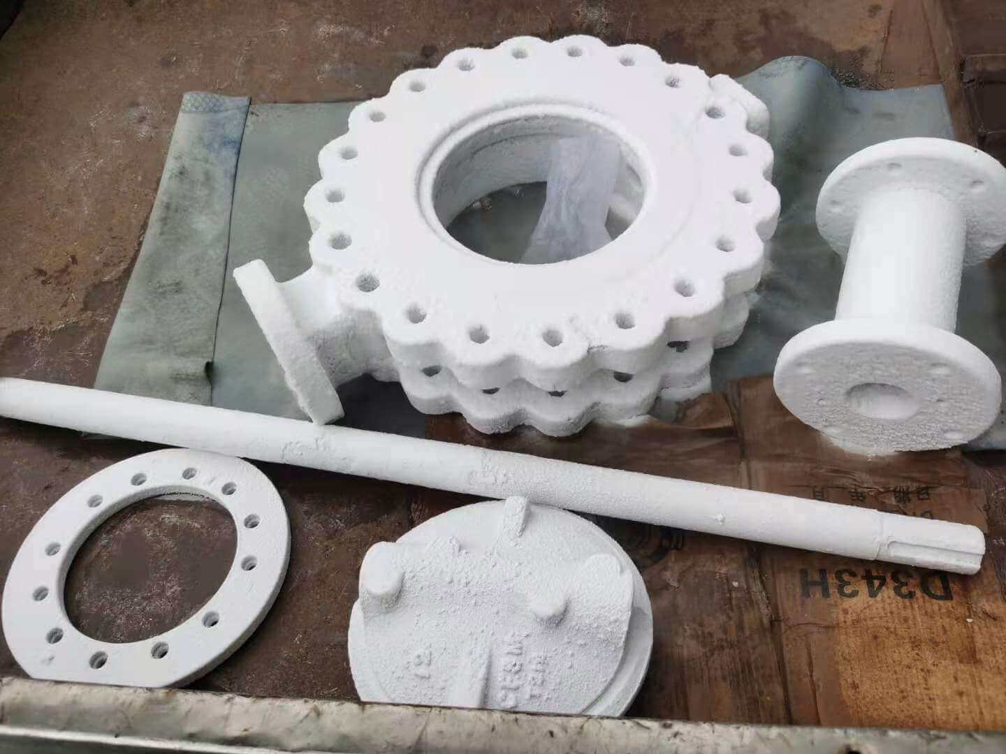
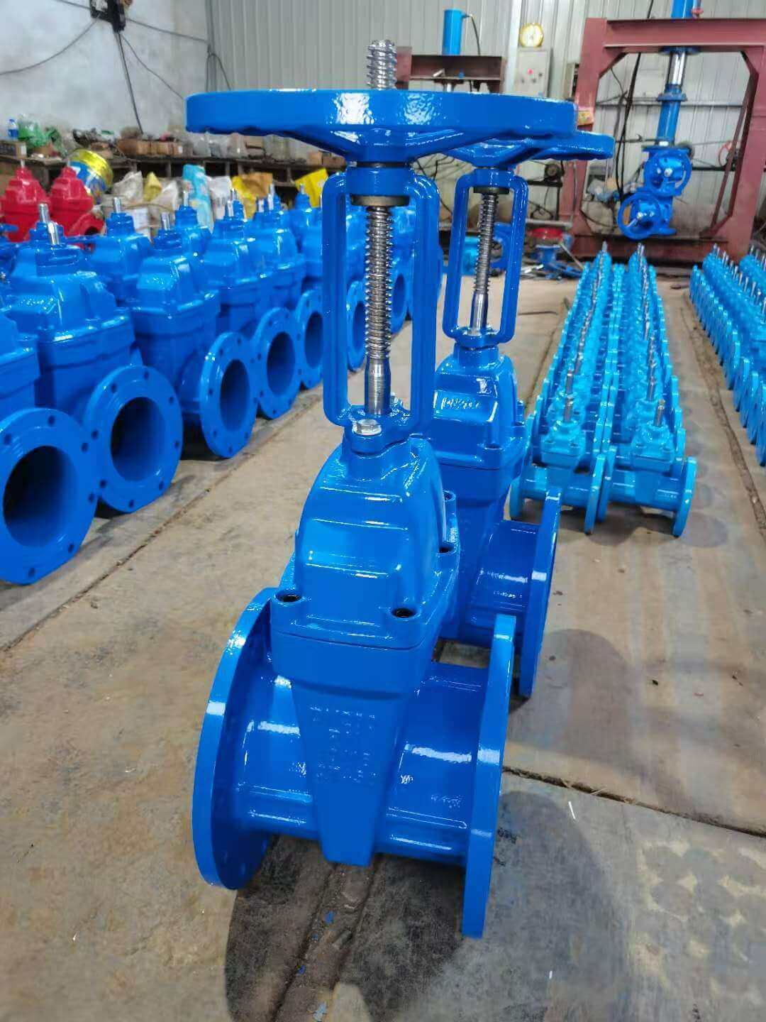
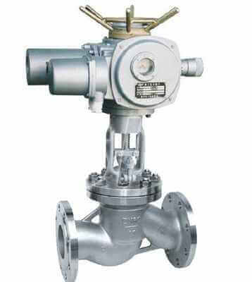
triple offset valve parts-after-cryogenic process
Requirements for sealing performance of low temperature triple eccentric butterfly valve:
There are two main reasons for the leakage of the low temperature triple eccentric butterfly valve, one is internal leakage; the other is external leakage.
1. Internal leakage of butterfly valve:
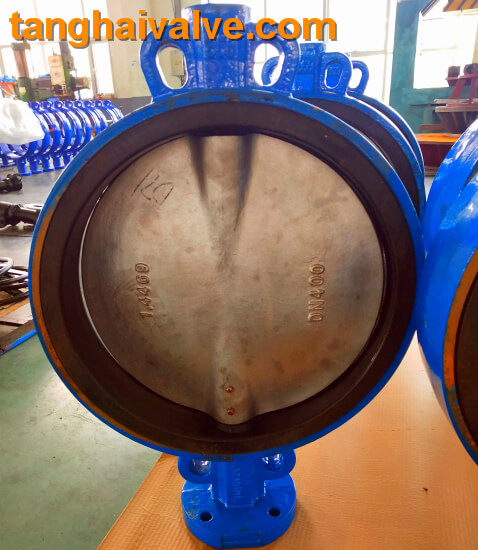
The main reason for the internal leakage of the valve is the deformation of the sealing pair in the low temperature state. When the temperature of the medium drops to a phase change of the material, the volume changes, which causes the sealing surface with high grinding accuracy to warp and deform, resulting in poor low-temperature sealing. We conducted a low temperature test on the DN250 valve. The medium was liquid nitrogen (-196 ℃) and the butterfly plate material was 1Cr18Ni9Ti (without low temperature treatment). It was found that the sealing surface warped and deformed up to about
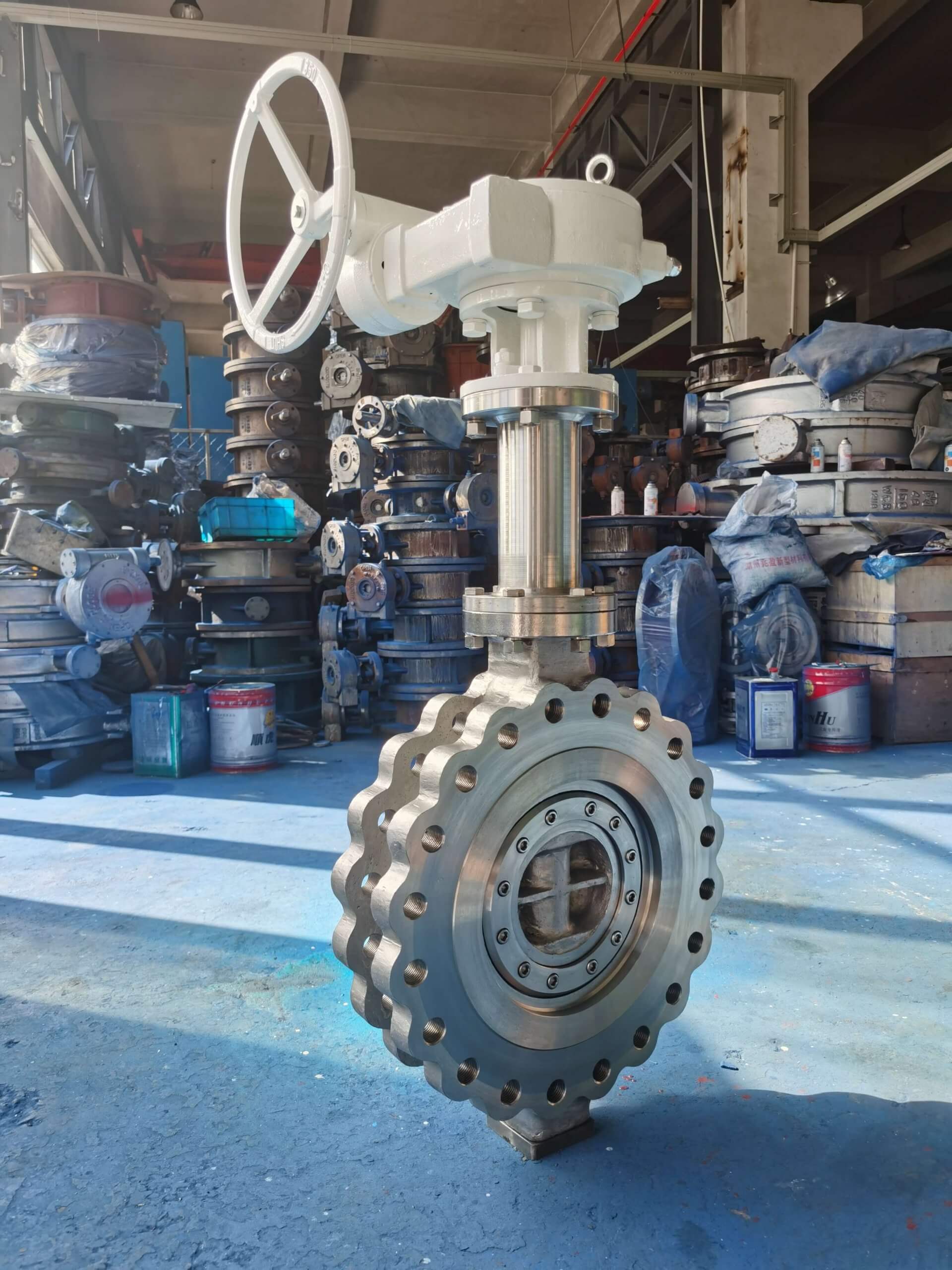
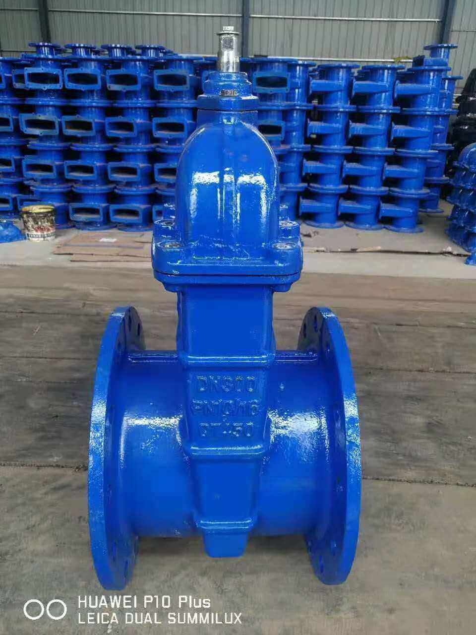
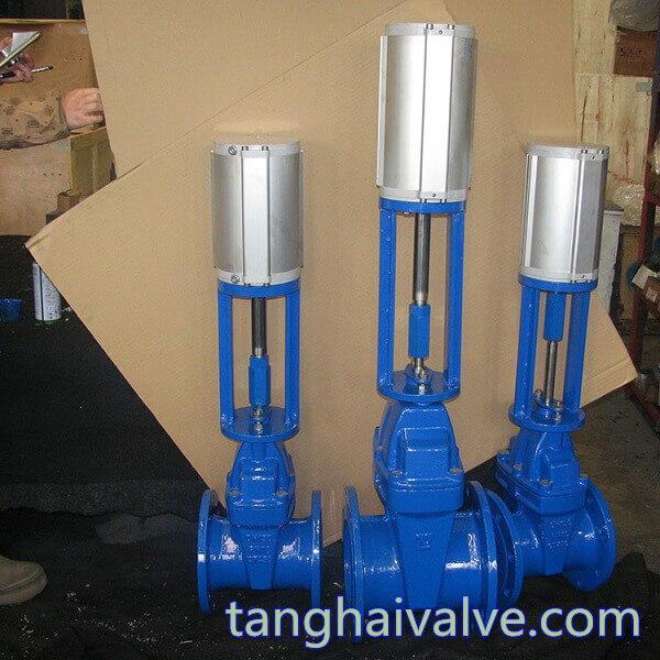
cryogenic triple offset butterfly valve 1
0.12mm, which is the main cause of internal leakage. And if the plane seal of the butterfly valve is changed to a cone seal. The valve seat is an oblique cone ellipse sealing surface, which forms a sealing pair with a round elastic sealing ring embedded on the butterfly plate. The sealing ring can float radially in the butterfly plate groove. When the valve is closed, the elastic sealing ring first contacts the short axis of the elliptical sealing surface. As the valve stem rotates, the sealing ring is gradually pushed inward, forcing the elastic ring to contact the long axis of the oblique cone surface, and finally the elastic sealing ring All contact with the oval sealing surface. Its sealing is achieved by the deformation of the elastic ring. Therefore, when the valve body or butterfly plate is deformed at low temperature, it will be absorbed and compensated by the elastic sealing ring, and leakage and jamming will not occur. When the valve is opened, this elastic deformation disappears immediately, and there is basically no relative friction during the opening and closing process, so the service life is long.
2. Leakage of butterfly valve:
One is that when the valve and the pipeline are connected by flanges, leakage occurs due to the unsynchronized contraction and relaxation of the connecting gasket, connecting bolts, and connecting materials at low temperatures. Therefore, we changed the connection between the valve body and the pipeline from a flange connection to a welded structure to avoid low temperature leakage. The second is leakage at the valve stem and packing. Generally, most valve packing adopts F4 because of its good self-sliding performance, low friction coefficient (friction coefficient for steel f=0.05 ~ 0.1), and unique chemical stability, so it is widely used. However, F4 also has shortcomings. First, the tendency of cold flow is large; second, the linear expansion coefficient is large, and the cold shrinkage at low temperature causes leakage, which causes a large amount of ice at the valve stem, so that the valve fails to open. The low-temperature triple-eccentric butterfly valve developed for this purpose adopts a self-shrinking sealing structure, that is, taking advantage of the large expansion coefficient of F4, and achieves the purpose of sealing at room temperature and low temperature through the reserved gap.
Design requirements for low temperature triple eccentric butterfly valve body and stem bushing:
1. The structure and shape of the cryogenic valve shell. The correct selection of materials is of great significance to the normal and reliable operation of the valve. Compared with the stop valve and gate valve, the structural characteristics of the butterfly valve not only avoid the irregular shape and uneven shell wall thickness, which can cause problems at low temperatures. Due to the small size of the butterfly valve, the shape of the valve body is basically symmetrical, so the heat capacity is small; the pre-cooling consumption is also small; the shape is regular and it is convenient to take measures to keep the valve cold. ,
2. Selection of stem bushing: Some low-temperature triple-eccentric butterfly valves are in operation, the rotating parts of the valve are sticky, and seizure occurs from time to time. The main reason is: unreasonable selection of matching materials, too small pre-cooling clearance, and processing Causes such as low accuracy. In the development of cryogenic valves, a series of measures have been taken to prevent the occurrence of the above phenomena. For the upper and lower bushings of the valve stem, SF-1 type composite bearings with low friction coefficient and self-lubricating properties are selected, which can be suitable for some special needs of cryogenic valves. The metal-sealed butterfly valve has the characteristics that some ordinary valves do not have, especially the small flow resistance, reliable sealing, rapid opening and closing, and long service life. The triple eccentric metal sealing butterfly valve is sealed by the deformation of the elastic ring, so it does not need to rely on the force of the medium, so it can be used for two-way sealing.
Related information: The difference of cryogenic valve and ordinary temperature valve; Cryogenic valve principle |standard |illustration |selection
TH Valve is a professional manufacturer of butterfly valve, gate valve, check valve, globe valve, knife gate valve, ball valve with API, JIS, DIN standard, used in Oil, Gas, Marine industry, Water supply and drainage, fire fighting, shipbuilding, water treatment and other systems, with Nominal Diameter of DN50 to DN1200, NBR/EPDM/VITON, Certificates & Approvals: DNV-GL, Lloyds, DNV, BV, API, ABS, CCS. Standards: EN 593, API609, API6D