The sealing characteristics and principle of eccentric butterfly valve
Basic knowledge of eccentric butterfly valve: eccentric butterfly valve, also called offset butterfly valve; Eccentric butterfly valves can be divided into various types, generally single eccentric sealing butterfly valves, double eccentric sealing butterfly valves, and triple eccentric sealing butterfly valves.
Features of single eccentric sealing butterfly valve:
In order to solve the problem of squeezing between the butterfly plate and the valve seat of the concentric butterfly valve, a single eccentric butterfly valve was produced. Disperse and reduce the excessive squeezing between the upper and lower ends of the butterfly plate and the valve seat. However, because the single eccentric structure does not disappear during the entire opening and closing process of the valve, the scratching phenomenon between the butterfly plate and the valve seat has not disappeared, and the application range is similar to that of the concentric butterfly valve, so it is not used much.
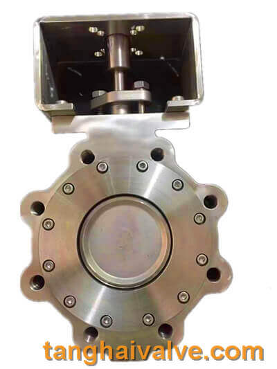
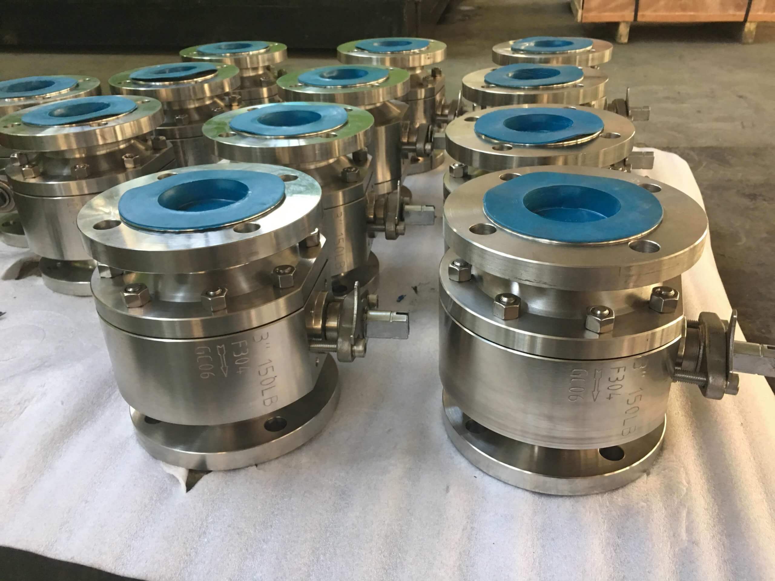
Double eccentric-lug butterfly valve-D72F-150lbP-stainless steel (4)
The single eccentric sealing butterfly valve has the following characteristics:
1. It has a sealing structure with reliable performance and long service life.
2. It has a truss structure with small flow resistance, good rigidity and small pressure loss.
3. The valve plate sealing ring is easy to replace and easy to maintain.
4. The valve plate sealing ring adopts a “T”-shaped structure, and the sealing pair is linearly sealed.
5. The bottom end of the valve adopts bimetal thrust washer, which has excellent thrust performance.
6. The valve can be installed vertically or horizontally, with good applicability.
7. This type of valve is recommended to be used in one direction, and it can be used in two directions when the reverse sealing requirements are not strict.
8. When the valve is completely closed, the leakage of the seal test is zero.
9. Replace the valve plate sealing ring, O-ring, valve body, valve plate, shaft and other materials, which can be applied to a variety of media and different temperatures.
Features of double eccentric sealing butterfly valve:
On the basis of the single eccentric butterfly valve, the double eccentric butterfly valve is the most widely used double eccentric butterfly valve. Its structural feature is that the axis of the valve stem deviates from the center of the butterfly plate and the center of the body. The double eccentric effect enables the butterfly plate to be released from the valve seat immediately after the valve is opened, which greatly eliminates unnecessary excessive extrusion and scratching of the butterfly plate and the valve seat, reduces the opening resistance, reduces wear and improves The life of the valve seat is improved. The scraping is greatly reduced, and at the same time, the double eccentric butterfly valve can also use a metal seat, which improves the application of the butterfly valve in the high temperature field. But because its sealing principle is a positional sealing structure, that is, the sealing surface of the butterfly plate and the valve seat is in line contact, and the elastic deformation caused by the butterfly plate squeezing the valve seat produces a sealing effect, so the closed position is very demanding (especially metal Valve seat), low pressure bearing capacity, which is why traditionally people think that butterfly valves are not resistant to high pressure and have large leakage.
The main features of the double eccentric butterfly valve are as follows:
1. Adopting full flow design, not affected by impurity jamming. The conjoined “O”-shaped sealing line at both ends makes the pipeline installation without gaskets and maintains a reliable seal. Different materials can be selected according to different usage requirements.
2. The butterfly plate material adopts streamlined design, which can be used in two directions, with low flow resistance and excellent flow characteristics.
3. The shaft pin adopts the unpinning structure, which can tightly combine the butterfly valve stems without weakening the strength of the shaft and has good interchangeability.
4. The valve body connection can be applied to ANSI125/150, DIN2501 PN10/16, JISB2210 10K, JIS G5527 7.5K standards.
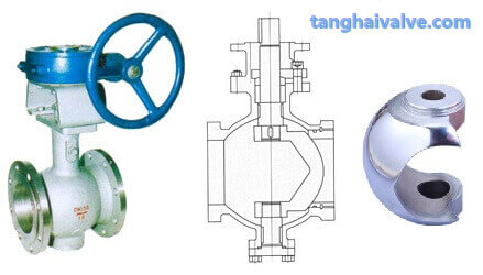
Features of triple eccentric sealing butterfly valve:
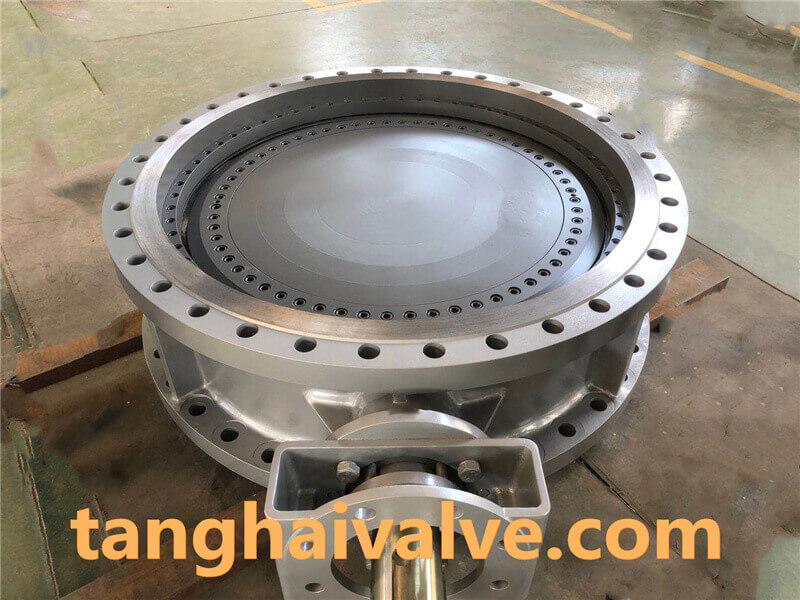
triple offset butterfly valve-double flange- (4)
1. API specifications
2. Double safety structure
3. No dead zone design
4. Body valve seat structure
5. Thin layer valve seat structure
6. Replaceable seal pair
7. Balanced fixed structure
8. Intrinsic refractory structure
9. High sealing packing structure
The structural feature of the triple eccentric butterfly valve is that while the double eccentric valve stem axis position is eccentric, the conical axis of the butterfly plate sealing surface is skewed to the cylinder axis of the body, that is to say, after the third eccentricity, the butterfly plate seals The cross-section is no longer a true circle, but an ellipse, and the shape of the sealing surface is therefore asymmetrical. One side is inclined to the center line of the body, and the other side is parallel to the center line of the body. The biggest feature of this third eccentricity is that the sealing structure is fundamentally changed. It is no longer a positional seal, but a torsion seal, that is, it does not rely on the elastic deformation of the valve seat, but completely relies on the contact surface pressure of the valve seat to achieve the seal. Therefore, the problem of zero leakage of the metal valve seat is solved in one fell swoop, and because the contact surface pressure is proportional to the medium pressure, the high pressure and high temperature resistance is also solved. Since its inception, the triple eccentric butterfly valve itself has undergone a process of self-improvement and continuous development in order to meet the increasingly severe requirements of working conditions. Even if the highest zero leakage is required, the triple eccentric butterfly valve can theoretically be achieved, but in fact it still relies on careful design and precision manufacturing.
Related knowledge: features of eccentric butterfly valve; Installation instructions of double eccentric butterfly valve
Related products: Electric triple eccentric butterfly valve Pneumatic triple eccentric butterfly valve
TH Valve is a professional manufacturer of butterfly valve, gate valve, check valve, globe valve, knife gate valve, ball valve with API, JIS, DIN standard, used in Oil, Gas, Marine industry, Water supply and drainage, fire fighting, shipbuilding, water treatment and other systems, with Nominal Diameter of DN50 to DN1200, NBR/EPDM/VITON, Certificates & Approvals: DNV-GL, Lloyds, DNV, BV, API, ABS, CCS. Standards: EN 593, API609, API6D