Globe valve Model Compilation Instructions and Representation Method
Model Compilation Instructions for Globe Valves | Representation Method
Compilation instructions for cut-off valve model Description method of cut-off valve model Compilation instructions for cut-off valve model: Cut-off valve, also known as cut-off valve, is a forced-sealing valve. According to the domestic valve model standard, the model of the globe valve is represented by the valve type, drive mode, connection mode,

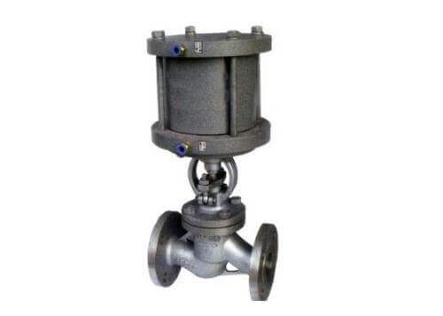
Globe valve (9)
structure form, sealing material, nominal pressure, and valve body material code. The model of the globe valve is related to the correct understanding of the globe valve product, the importance of the type selection, and the guarantee of the safety of the working conditions. Some of the codes in the following globe valve model compilation are omitted, mainly for the model description of the existing globe valve products. If the material and structure of the customized cut-off valve product changes, please select according to the valve programming method, or call for details.
Representation method of globe valve model:
Additional code for stop valve: W means bellows, D means low temperature, B means heat preservation;
1) Type code of globe valve: J means globe valve;
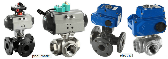
2) Stop valve transmission mode: manual without code, 5 bevel gear, 6 pneumatic, 9 electric;
3) Connection mode of stop valve: 4 flange connection, 6 welding;
4) The structure of the globe valve: 1 straight-through type, 2 Z-type straight-through, 3 three-way, 4-angle type, 5 Y-type DC type, 6 balanced straight-through type, 7 balanced angle type, 8-pin type;
5) Seal material of globe valve: F fluorine rubber, H stainless steel, N nylon plastic, Y cemented carbide, M Monel alloy, W valve body directly processed;
6) The nominal pressure of the shut-off valve: 16 means that the pressure of 1.6mpa is 16 kilograms, PN1.6-32mpa, IN150LB-1500LB, 5-63K;
7) Globe valve body material: A titanium alloy, C carbon steel, I chromium molybdenum steel, P stainless steel 304,
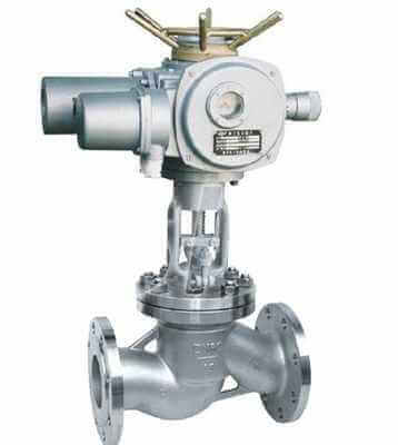
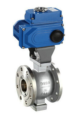
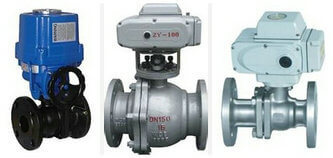
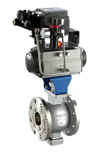
electric globe valve
R stainless steel 316;
Example of model compilation of globe valve:
J941H-16C Electric Flange Globe Valve
1. J: indicates the stop valve;
2. 9: indicates that the transmission mode is electric;
3. 4: The connection method is flange connection;
4. 1: The structure is a straight flow channel;
5. H: The sealing material is stainless steel;
6. 16: Indicates that the nominal pressure is 1.6MPa;
7. C: Indicates that the valve body material is carbon steel.
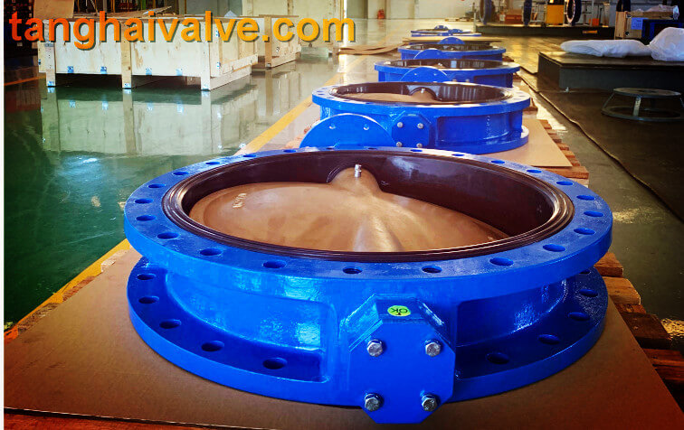
TH Valve is a professional manufacturer of butterfly valve, gate valve, check valve, globe valve, knife gate valve, ball valve with API, JIS, DIN standard, used in Oil, Gas, Marine industry, Water supply and drainage, fire fighting, shipbuilding, water treatment and other systems, with Nominal Diameter of DN50 to DN1200, NBR/EPDM/VITON, Certificates & Approvals: DNV-GL, Lloyds, DNV, BV, API, ABS, CCS. Standards: EN 593, API609, API6D
Related valve model:
Representation method of butterfly valve model;
The working principle and characteristics of the globe valve;
Representation method of electric gate valve model;
Gate valve model meaning and representation method