How to choose concentric |double eccentric |triple eccentric butterfly valve
The difference in butterfly valve structure distinguishes four types of butterfly valves, namely: concentric butterfly valve, single eccentric butterfly valve, double eccentric butterfly valve and triple eccentric butterfly valve. What is the concept of this eccentricity? How to decide when to use concentric butterfly valve, when to use single eccentric
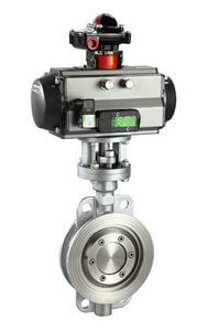
D673H-16C-stainless steel pneumatic triple eccentric butterfly valve
butterfly valve, when to use double eccentric butterfly valve and triple eccentric butterfly valve? Many users are not particularly clear. We might as well share together.
Concentric butterfly valves, single eccentric butterfly valves, double eccentric butterfly valves and triple eccentric butterfly valves reflect the process of opening and closing more and more labor-saving, and the sealing surface wear is getting smaller and smaller. By setting the position of the shaft of the butterfly valve valve plate, the sealing and opening state of the butterfly valve can be changed. Under the same conditions, the torque of the valve is greater than one at each opening. When the valve is opened, the angle required for the valve plate to be separated from the seal is smaller than one.
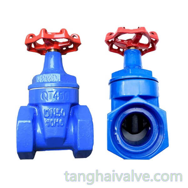
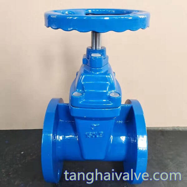
The structural feature of the concentric butterfly valve is that the shaft center of the valve stem, the center of the butterfly plate, and the center of the valve body are in the same position. Generally, if you can use concentric butterfly valves in principle, use concentric butterfly valves as much as possible. Because the concentric butterfly valve does not require high sealing performance in terms of structure or operation, it is a conventional product. In order to overcome squeezing, scratching, and to ensure the sealing performance, the seat of the concentric butterfly valve is basically made of rubber or polytetrafluoroethylene and other elastic materials,
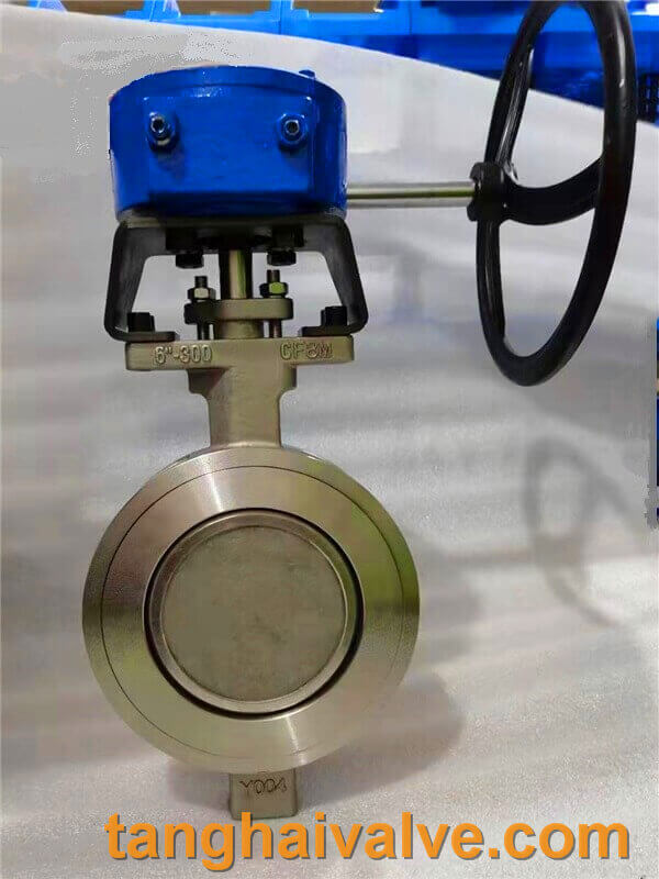
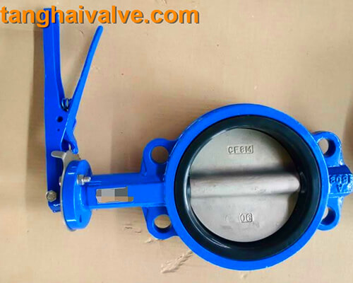
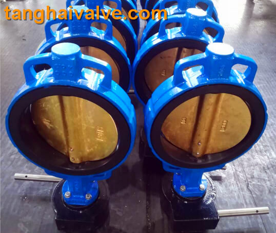
Double eccentric-wafer butterfly valve-D372F-150lbP-stainless steel (1)
which is a soft sealing butterfly valve. This makes the concentric butterfly valve subject to temperature restrictions in use. In order to solve the problem of the squeezing of the butterfly plate and the valve seat of the concentric butterfly valve, a single eccentric butterfly valve was also produced. Its structural feature is that the shaft center of the valve stem deviates from the center of the butterfly plate.
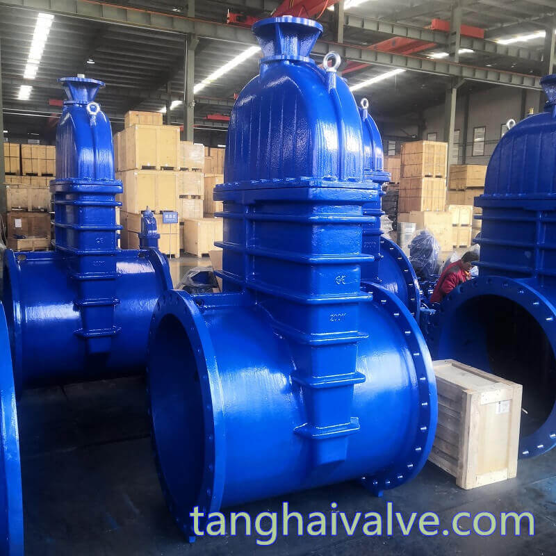
Double eccentric butterfly valve is the most widely used. Its structural feature is that the shaft center of the valve stem deviates from the center of the butterfly plate and the center of the valve body. It deviates from the two center positions so it is called a double eccentric butterfly valve. Many double eccentric butterfly valves are line-sealed. When the sealing surface is closed, friction occurs between the disc and the valve seat, and the sealing effect is very good. It has the characteristics of small area and strong pressure. After the valve is opened, the butterfly plate can be quickly separated from the valve seat, which greatly eliminates unnecessary excessive squeezing and scratching of the butterfly plate and the valve seat, reduces the opening resistance, reduces the wear, and improves the life of the valve seat.
The triple eccentric butterfly valve is eccentric for the third time on the basis of the double eccentric butterfly valve. The shape of the sealing pair is not a positive cone, but an oblique cone. Mostly short-distance force and face seal. The stem shaft of the triple eccentric butterfly valve is a three-section shaft structure. The two shaft sections of this three-section shaft valve stem are concentric, and the center line of the central section shaft deviates from the axis of both ends by a center distance, and the butterfly plate is installed in the middle On the shaft section. Such an
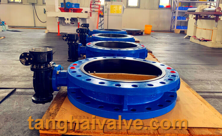
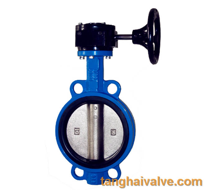
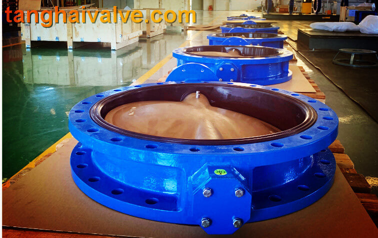
U-type flange butterfly valve, ductile iron, DI, center line,
eccentric structure makes the butterfly plate a double eccentric shape when in the fully open position, and a single eccentric shape when the butterfly plate rotates to the closed position. Due to the effect of the eccentric shaft, when it is close to closing, the butterfly plate moves a distance into the sealing cone surface of the valve seat, and the butterfly plate matches the sealing surface of the valve seat to achieve reliable sealing performance. It makes up for the contradiction that the hard seal has poor sealing, and the soft seal has good sealing effect but is not resistant to high temperatures. When to use a concentric butterfly valve and when to choose a double eccentric butterfly valve or a triple eccentric butterfly valve, it mainly depends on the usage habits and budget. If it is not for extreme working conditions, concentric butterfly valves can generally be selected, and concentric butterfly valves should be used as much as possible. Because the concentric butterfly valve is simple in structure and relatively economical in price.
TH Valve is a professional manufacturer of butterfly valve, gate valve, check valve, globe valve, knife gate valve, ball valve with API, JIS, DIN standard, used in Oil, Gas, Marine industry, Water supply and drainage, fire fighting, shipbuilding, water treatment and other systems, with Nominal Diameter of DN50 to DN1200, NBR/EPDM/VITON, Certificates & Approvals: DNV-GL, Lloyds, DNV, BV, API, ABS, CCS. Standards: EN 593, API609, API6D
Related news/knowledge:
The sealing characteristics and principle of eccentric butterfly valve
The Basic Knowledge of Butterfly Valves
Classification and features of Eccentric butterfly valves
Selection and application of eccentric butterfly valve