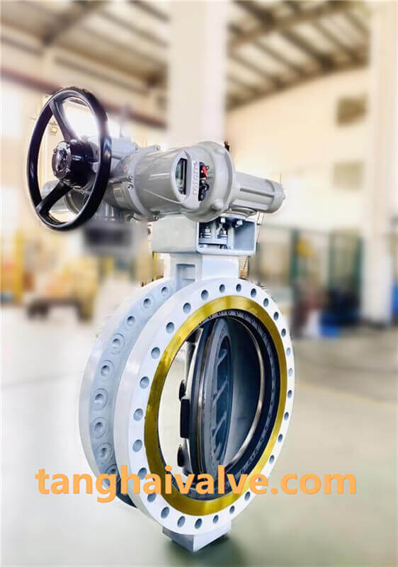
Wafer type dual plate check valve: metal seated vs resilient seated
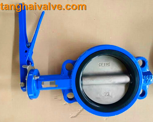
Wafer dual plate check valve is used for pure pipelines and industrial, environmental protection, water treatment, high-rise building water supply and drainage pipelines, to prevent the reverse flow of the medium. The check valve adopts a clamp type, the butterfly plate is two semicircles, and it adopts a spring for forced reset. The sealing surface can be built-up welding wear-resistant material or rubber lining, with a wide range of use and reliable sealing.
The check valve opening and closing parts are opened or closed automatically by the flow and force of the medium to prevent the medium from flowing back. The valve is called the check valve. Check valves belong to the category of automatic valves, which are mainly used in pipelines where the medium flows in one direction, and only allow the medium to flow in one direction to prevent accidents.
According to the structure of the check valve, it can be divided into three types: lift check valve, swing check valve and butterfly check valve. Lift check valves can be divided into two types: vertical and horizontal. Swing check valves are divided into three types: single valve, double valve and multi valve. The butterfly check valve is a straight-through type. The above-mentioned check valves can be divided into three types in connection form: threaded connection, flange connection and welding. A check valve is a valve that can automatically prevent fluid from flowing back. The disc of the check valve is opened under the action of fluid pressure, and the fluid flows from the inlet side to the outlet side. When the pressure on the inlet side is lower than that on the outlet side, the valve flap is
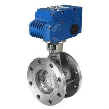
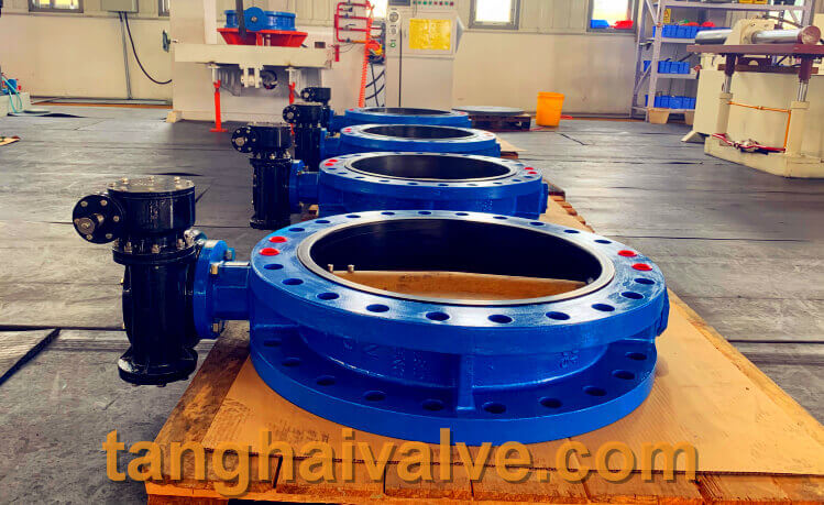
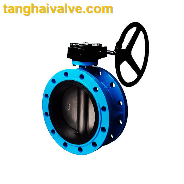
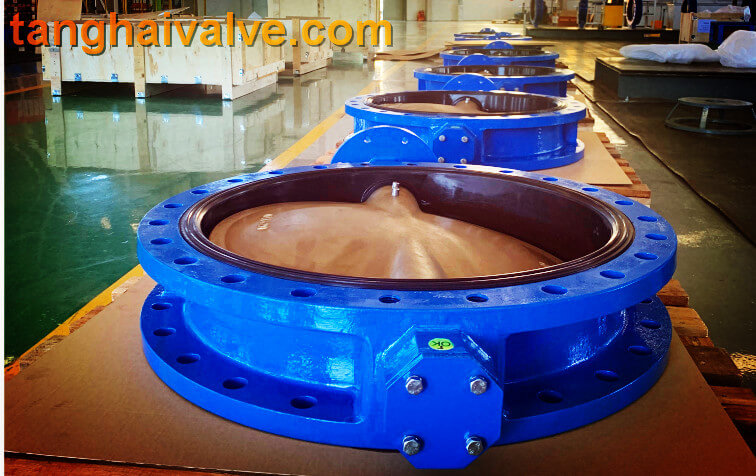
H46-double flanged dual plate check valve-metal seated
automatically closed under the action of the fluid pressure difference, its own
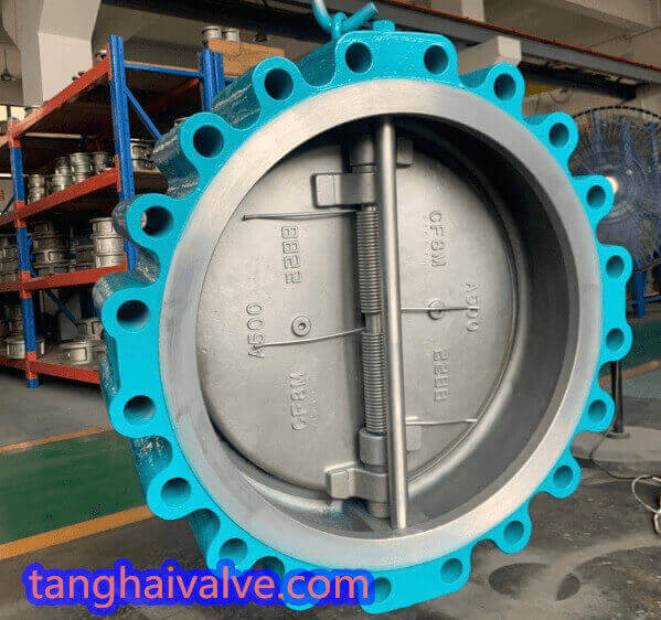
lug type dual plate check valve metal seated (3)
gravity and other factors to prevent the fluid from flowing back.
klug type dual plate check valve metal seated (1)The dual plate check valve is divided into flange dual plate check valve, lug dual plate check valve and wafer dual
plate check valve.
Classification of wafer dual plate check valves: hard-seal wafer dual plate check valve and soft-seal wafer dual plate check valve; of which soft-seal wafer check valve is divided into full-lined soft-seal wafer check valve and Semi-lined/normal soft-seal wafer dual plate check valve.
Features of Wafer dual plate Check Valve:
- Simple structure and light weight, especially suitable for low-pressure large-diameter pipelines;
- The paired clamp connection mode, the production process is simple, and the disassembly and assembly are convenient;
- The check valve adopts the clamp type, the butterfly plate is two semicircles, and the spring is forced to reset. The sealing surface can be built-up welding wear-resistant material or rubber lining, with a wide range of use and reliable sealing.
Model: H76X/H76H/H76W
Name: Wafer dual plate check valve
Please refer to the main technical parameters and spare parts materials:
https://www.tanghaivalve.com/wafer-type-double-disc-swing-check-valve-introduction/
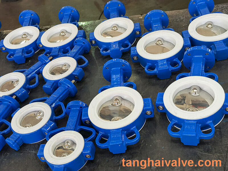
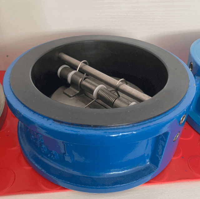
Product name: Wafer double plate check valve (soft seal)
National Standard Number: H76X
dual plates check valve photos-normal sealing (1)
Size range: DN40-DN1200
Pressure rating: PN10/16/25/40/64/100
Valve features: double valve plate design, short running track of the valve plate, spring load makes the valve plate close more quickly, effectively preventing water hammer
When the valve plate is opened, it is close to 90 degrees, and the pressure loss is small
Zero leakage
Size range: 2″ to 48″
Pressure range: 10bar-50 bar
Suitable flange: National standard or EN1092 PN10/PN16/PN25/PN40 or ANSI 125/150/300
Structure length: EN558 series 16, API594
Body material: gray cast iron, ductile iron, carbon steel, stainless steel, aluminum bronze
Valve plate material: ductile iron nickel-plated, stainless steel 201, stainless steel 304,
dual plates check valve photos- full rubber
stainless steel 316, aluminum bronze
Valve seat material: nitrile NBR, EPDM, oil and acid and alkali resistant fluorine rubber VITON-A, steam resistant fluorine rubber VITON-B, hard seal
Uses: Suitable for installation at the outlet of high-lift pumps, or as a bottom valve in front of the pump, suitable for water, sea water, steam, oil, chemicals, chlorine, oxygen, and steam. Can be installed horizontally or vertically.
Application scope:
It is suitable for industrial, environmental protection, sewage treatment, high-rise building water supply and drainage pipelines, etc. It can also be used for environmental systems with corrosive media such as power plants and steel plants gypsum slurry.
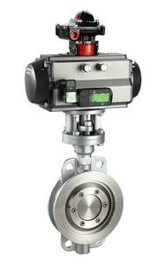
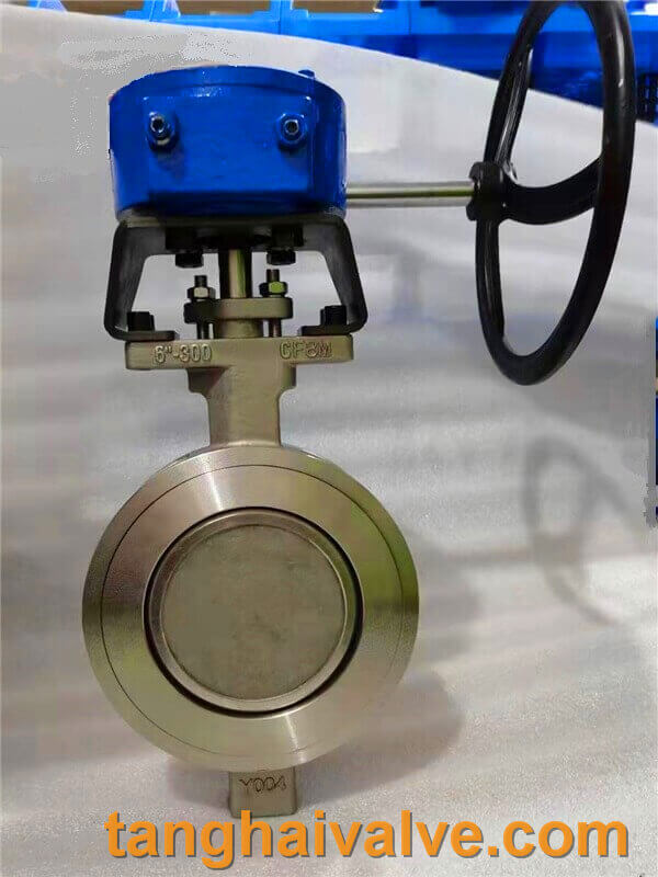
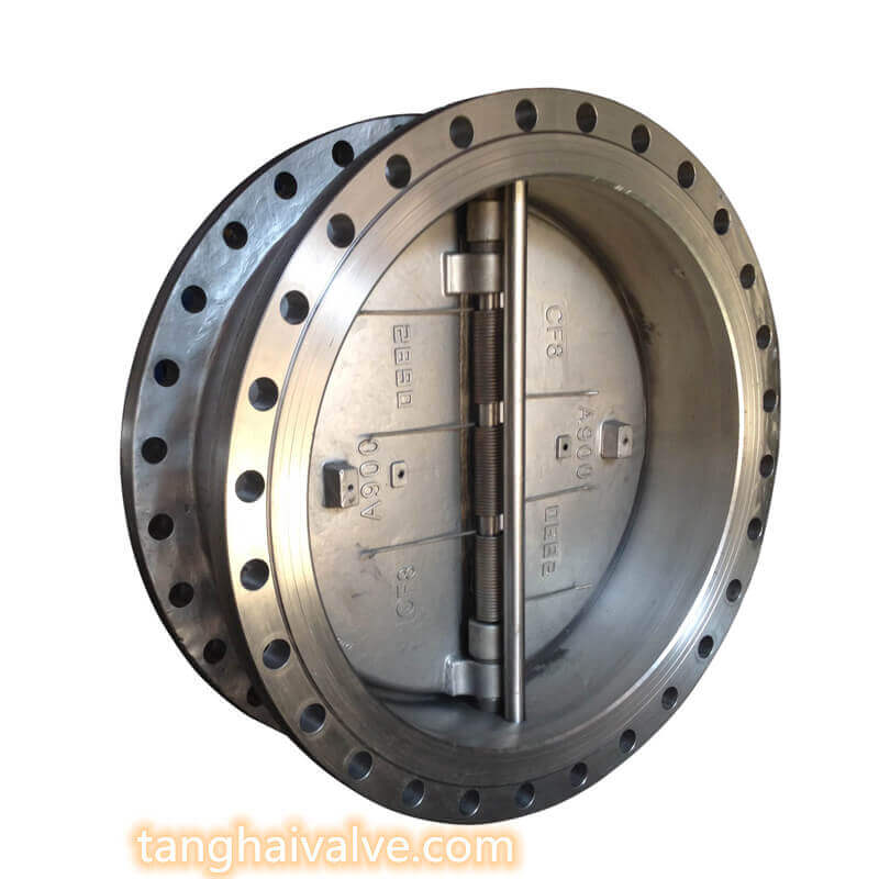
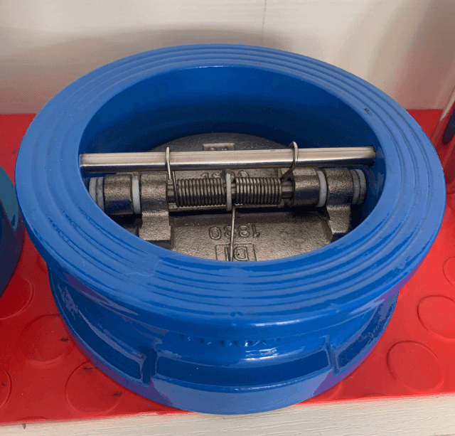
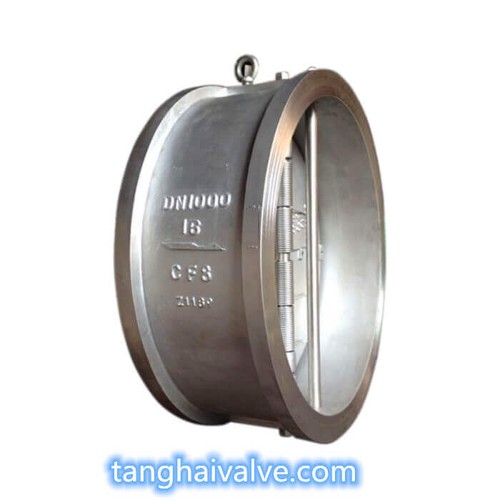
Product name: Wafer double plate check valve (metal seated)
National standard number: H76H(W)-16C(16P, 16R, 16RL)
Size range: DN40-DN1200
H76-wafer type dual plate check valve metal seated
Pressure rating: PN10/16/25/40/64/100
Temperature range: -20℃ -350℃
Body material: WCB, A105, CF8, CF3, CF8M.CF3M and other materials and special steel
Valve plate material: WCB, A105.2CR13, 304.304L.316.316L and other materials and special steel
Valve shaft material: A105.2CR13, 304.304L.316.316L and other materials and special steel
Valve seat material: 2CR13, 304.304L.316.316L, STL and other materials and special steel
Application range: water, steam, oil, nitric acid, acetic acid, strong oxidizing medium and urea and other media
More video for wafer dual plate check valve, please see below:
https://www.youtube.com/watch?v=pGrkznOd-JA
https://youtu.be/etwT8RX-S3Q
https://www.youtube.com/watch?v=XqRRI7o-LFI
TH Valve is a professional manufacturer of butterfly valve, gate valve, check valve, globe valve, knife gate valve, ball valve with API, JIS, DIN standard, used in Oil, Gas, Marine industry, Water supply and drainage, fire fighting, shipbuilding, water treatment and other systems, with Nominal Diameter of DN50 to DN1200, NBR/EPDM/VITON, Certificates & Approvals: DNV-GL, Lloyds, DNV, BV, API, ABS, CCS. Standards: EN 593, API609, API6D
Related news/knowledge:
 maintained under the working conditions of dirty media. The valve seal can be replaced without removing the valve, making the valve maintenance easier.