How many types of gate valves?
Types and classifications method of gate valves
Gate valve, also called slab valve, is mainly composed of valve body, bonnet, gate, valve stem, valve seat and sealing packing. It is one of the most common valve types in isolation valves. The main purpose of the gate valve is to cut off the fluid. For this reason, it is usually called a “cut off” valve or a “blocking” valve. There are many different structural forms of gate valves, and the types of sealing elements used in them are different. According to the
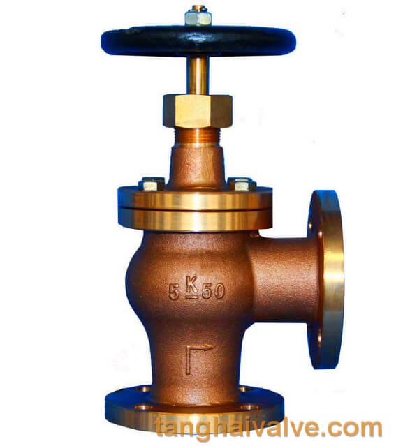
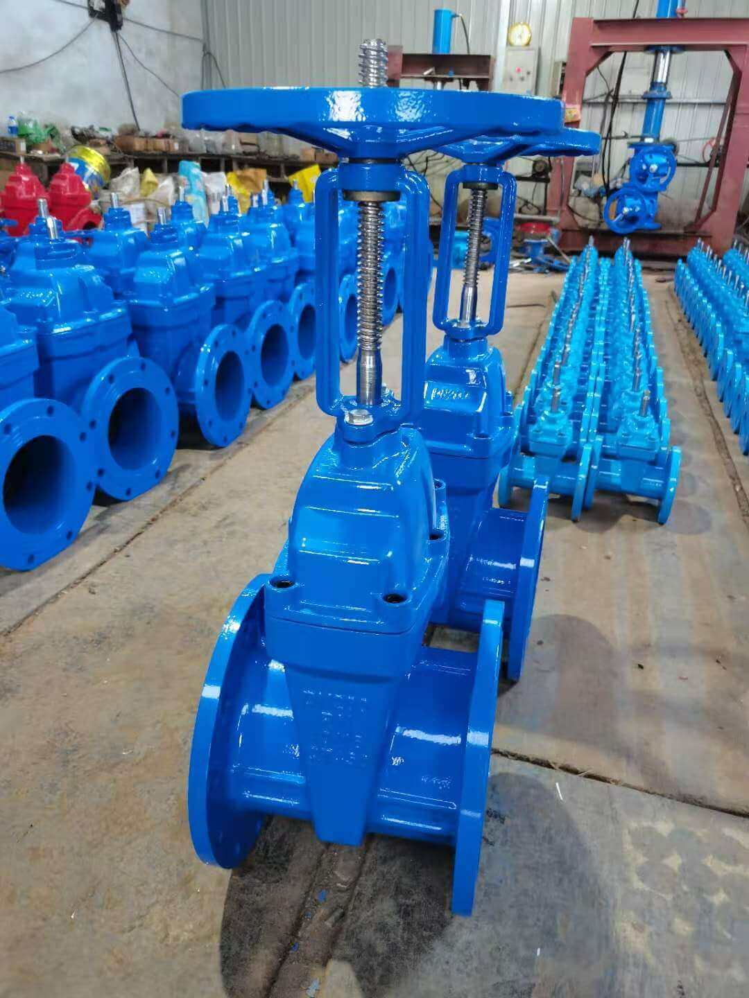
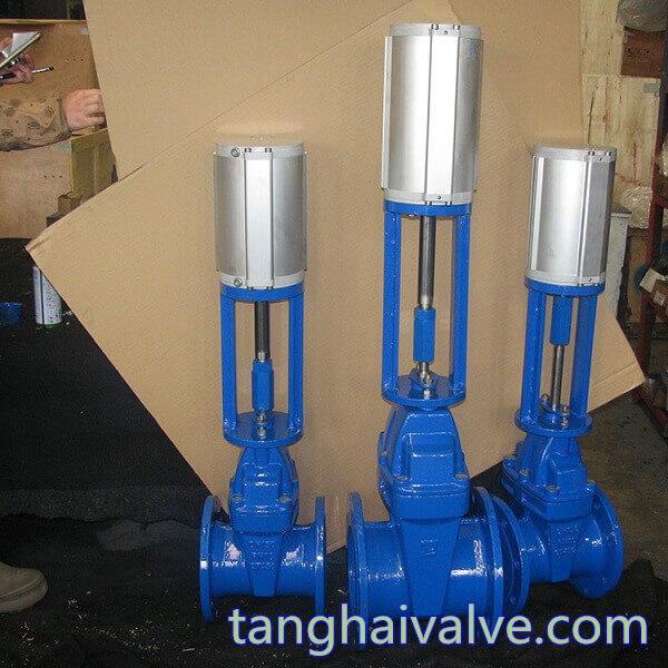
Socket ended resilient seated wedge gate valve-ductile iron (1)
structure of the sealing element, it can be divided into several different types.
Classified by valve stem:
According to the stem type, it can be divided into bright stem gate valve and dark stem gate valve. The valve stem is the operating part of the gate valve, and its function is to transmit the opening and closing force to the opening and closing parts.
1. The trapezoidal thread of the stem of the rising stem gate valve is placed outside the valve body and located on the upper part of the valve stem. By rotating the stem nut, the valve stem drives the gate plate to rise and fall synchronously to realize the opening and closing of the valve, so it is easy to identify the valve. Open and close state to avoid misoperation. Since the stem nut is outside the body cavity, it is conducive to lubrication, and the opening and closing state is intuitive and obvious, so it is widely used. However, in harsh environments, the exposed threads of the valve stem are susceptible to damage and corrosion, even affecting operation. Its disadvantage is that the height of the valve after opening is large, and a stroke is usually added to the original height of the valve, which requires a lot of operating space.
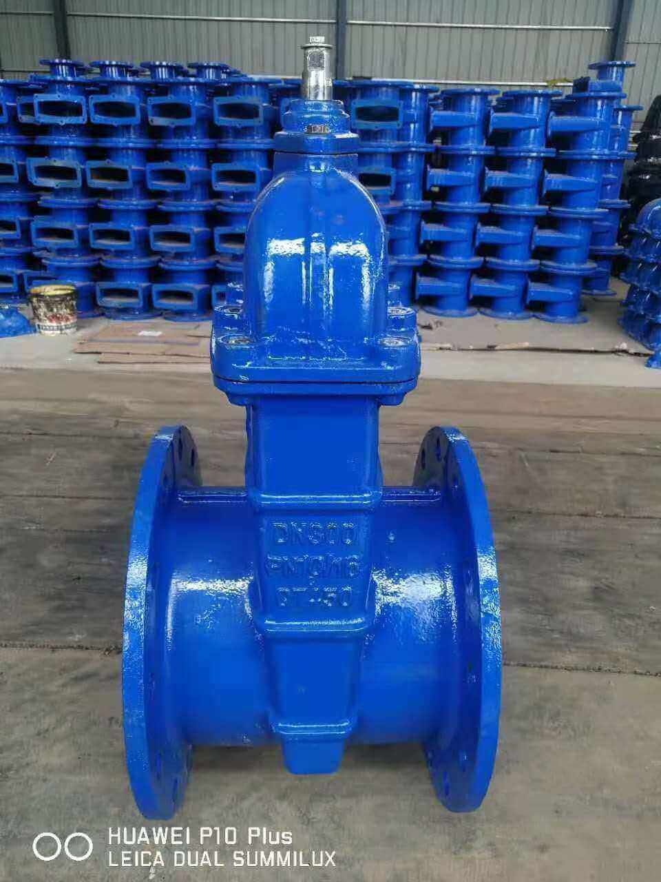
2. Dark stem gate valve is also called rotating stem gate valve (also called dark stem wedge gate valve). The stem nut is placed inside the valve body and is in direct contact with the medium. It is often fixed on the gate. Through the rotation of the valve stem, the valve stem nut drives the gate to move up and down to complete the opening and closing. Usually there is a trapezoidal thread at the bottom end of the valve stem. Through the thread at the bottom end of the valve and the guide groove on the valve disc, the rotary motion is changed into linear motion, that is, the operating torque is turned into operating thrust. Since the trapezoidal thread used for transmission is located inside the valve body, it is easily corroded by the medium and cannot be lubricated. The opening degree cannot be directly observed, and an indicating device is required. However, its valve stem does not move up and down, and requires a small operating space, so it is suitable for occasions with limited locations and dense pipelines.
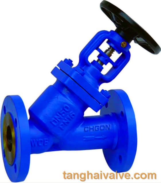
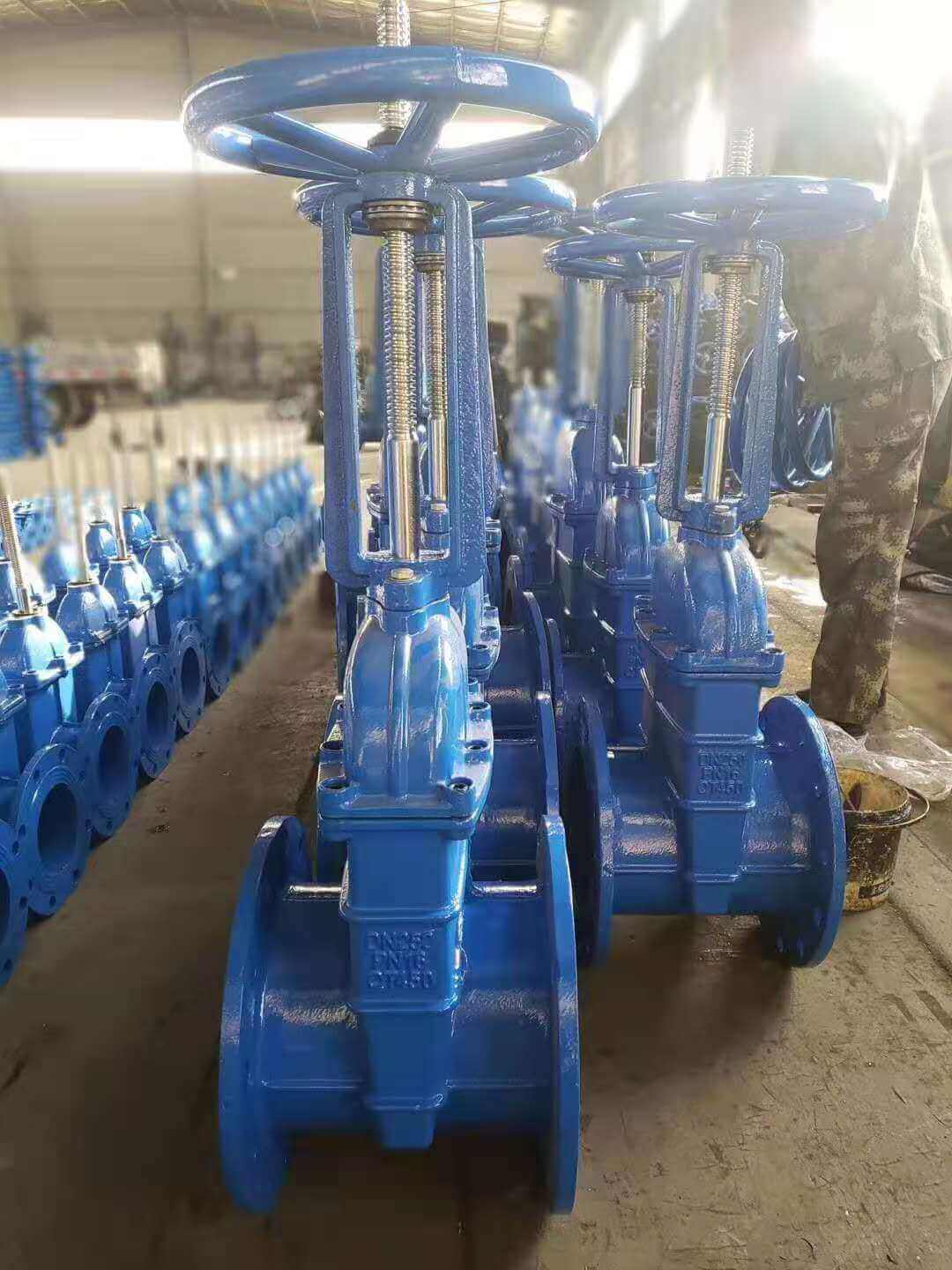
gate valve (3)
Classified by structure:
According to the structure type, it can be divided into two types: wedge gate valve and parallel gate valve. That is, a wedge-type gate valve is called a wedge gate valve, and a parallel gate valve is a flat gate valve.
1. The flat gate valve means that the sealing surface is parallel to the vertical centerline, so the sealing surface of the valve body and the gate plate are also parallel to each other. The most common type of this kind of gate valve is the double gate type. In order to make the valve body and the two sealing surfaces of the gate closely contact when closed, a double-sided thrust wedge is often used between the two gates. Most of them are used on low-pressure pipelines such as small pipelines. Parallel gate valves using single gates are also rare but rare.
2. Wedge gate valve means that the sealing surface is at a certain angle to the vertical centerline, that is, the two sealing surfaces are wedge-shaped gate valves. The wedge gate valve has single and double gate plates. The advantage of the double gate type is that the accuracy of the sealing and the angle is lower, the temperature change is not easy to make the gate wedged, and the sealing surface wear can be compensated with gaskets. The disadvantage is that the structure is complex, and it is easy to stick in dry media, and the main reason is that the upper and lower baffles are easy to fall off after years of corrosion.
Classification by other methods:
According to different standards: national standard gate valve, American standard gate valve, German standard gate valve, Japanese standard gate valve
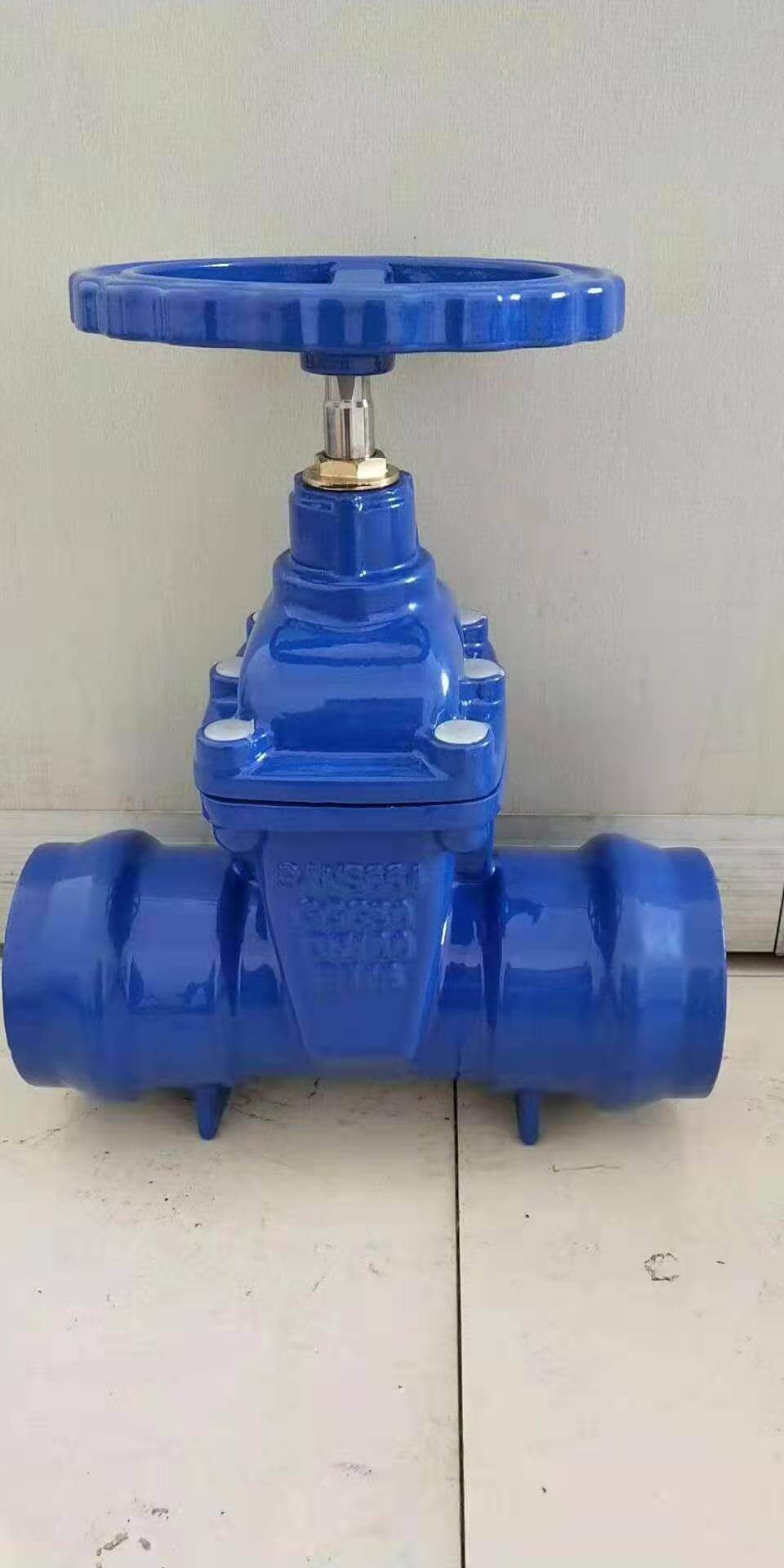
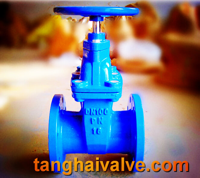
According to the connection method: flanged gate valve, welded gate valve, threaded gate valve (divided into internal thread and external thread)
According to pressure level: high pressure gate valve, low (medium) pressure gate valve According to driving mode: electric gate valve, pneumatic gate valve, manual gate valve
Classified by material: stainless steel gate valve, forged steel gate valve, cast steel gate valve, carbon steel gate valve, cast iron gate valve, copper gate valve (also divided into bronze gate valve, brass gate valve), ceramic gate valve, plastic gate valve
TH Valve is a professional manufacturer of butterfly valve, gate valve, check valve, globe valve, knife gate valve, ball valve with API, JIS, DIN standard, used in Oil, Gas, Marine industry, Water supply and drainage, fire fighting, shipbuilding, water treatment and other systems, with Nominal Diameter of DN50 to DN1200, NBR/EPDM/VITON, Certificates & Approvals: DNV-GL, Lloyds, DNV, BV, API, ABS, CCS. Standards: EN 593, API609, API6D
Related news /knowledge:
Pneumatic gate valve model preparation method;
Classification and advantages of gate valve;
Resilient seated socket end gate valve;
Representation method of electric gate valve model;