Gate valve, also called plate gate valve, is mainly composed of valve body, bonnet, disc, valve stem, valve seat and sealing packing. It is one of the most common valve types in isolation valves. The main purpose of the gate valve is to cut off the fluid. For this reason, it is usually called a “cut off” valve or a “blocking” valve. The gate valve has many different structural forms, and the sealing element structure used in it is different. According to the structure of the sealing element, it can be divided into several different types.
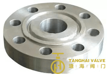
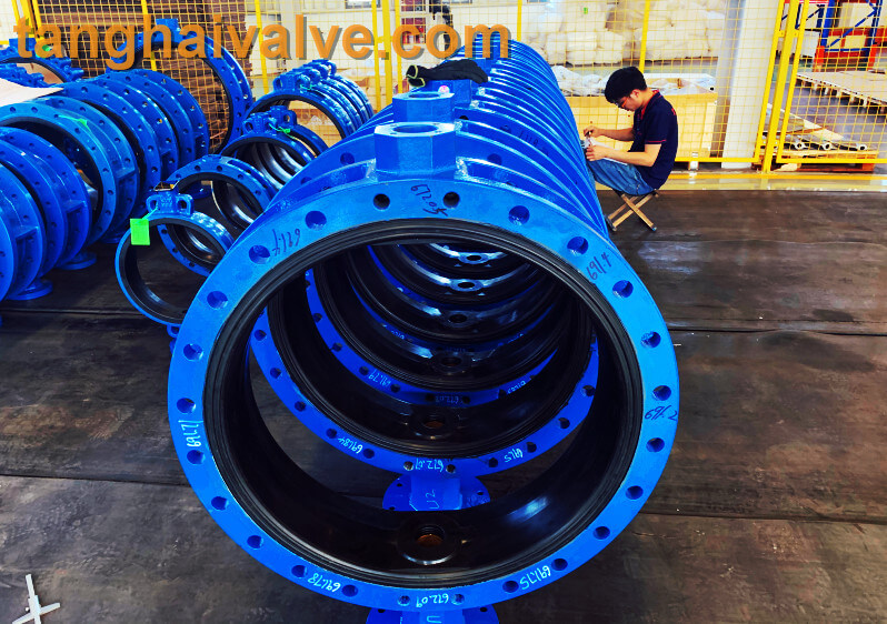
ductile iron soft seal gate valve-non rising stem
Classified by valve stem:
According to the stem type, it can be divided into rising-stem gate valve and non rising-stem gate valve. The valve stem is the operating part of the gate valve, and its function is to transmit the opening and closing force to the opening and closing parts.
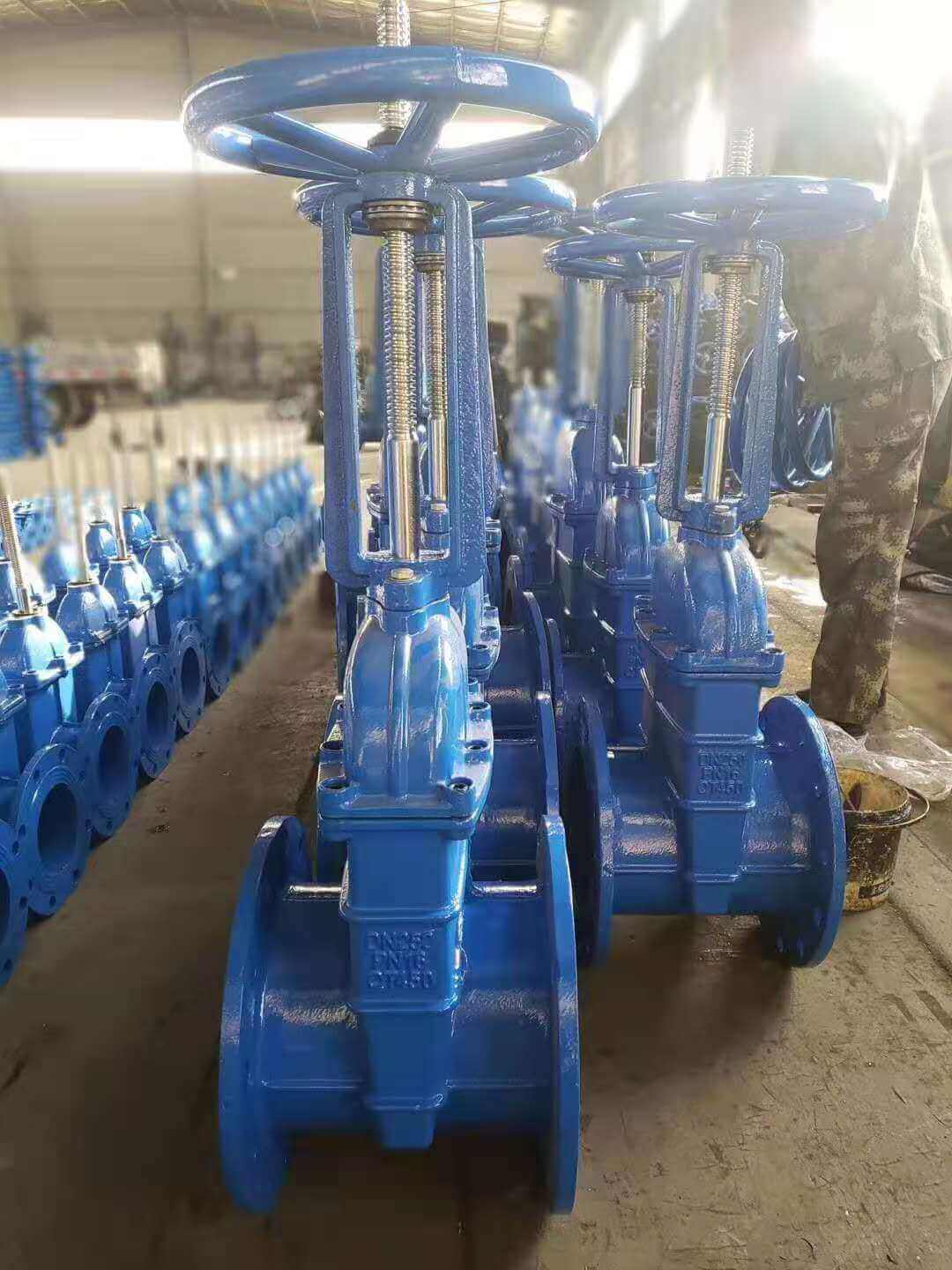
1. The trapezoidal thread of the rising-stem gate valve is placed outside the valve body and located on the upper part of the valve stem. By rotating the valve stem nut, the valve stem drives the disc to rise and fall synchronously to realize the opening and closing of the valve, so it is easy to identify the valve The opening and closing state of the machine can avoid misoperation. Since the stem nut is outside the body cavity, it is beneficial to lubrication, and the opening and closing state is intuitive and obvious, so it is widely used. However, in harsh environments, the exposed threads of the valve stem are vulnerable to damage and corrosion, even affecting operation. Its disadvantage is that the height of the valve after opening is large, usually a stroke is added to the original height of the valve, which requires a lot of operating space.
rising stem gate valve-OS&Y (3)
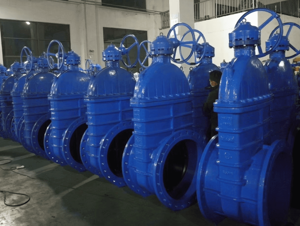
2. Non rising-stem gate valve is also called rotating stem gate valve (also called non rising-stem wedge gate valve). The stem nut is placed inside the valve body and is in direct contact with the medium and is often fixed on the disc. Through the rotation of the valve stem, the valve stem nut drives the disc to move up and down to complete the opening and closing. Usually there is a trapezoidal thread at the bottom end of the valve stem. Through the thread at the bottom end of the valve and the guide groove on the valve disc, the rotary motion is changed into linear motion, that is, the operating torque is turned into operating thrust. Since the trapezoidal thread for transmission is located inside the valve body, it is easily corroded by the medium and cannot be lubricated. The opening degree cannot be directly observed, and an indicating device is required. However, its valve stem does not move up and down, and requires small operating space, so it is suitable for occasions with limited locations and dense pipelines.
Classified by structure:
According to the structure type, it can be divided into two types: wedge gate valve and parallel gate valve. That is, the disc is a wedge type is called a wedge gate valve, and the disc is a parallel type is a flat gate valve.
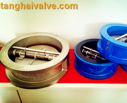
1. The flat gate valve means that the sealing surface is parallel to the vertical centerline, so the sealing surfaces on the valve body and the disc are also parallel to each other. The most common type of this kind of gate valve is the double disc type. In order to make the valve body and the two sealing surfaces of the disc tightly contacted when it is closed, a double-sided thrust wedge is often used between the two discs. It is mostly used in low pressure pipelines such as small pipelines. Parallel gate valves using a single disc are also available but rare.
2. Wedge gate valve means that the sealing surface is at a certain angle with the vertical center line, that is, the two sealing surfaces are wedge-shaped gate valves. The disc of wedge gate valve is single and double. The advantage of the double disc type is that the accuracy of the sealing angle is lower, the temperature change is not easy to make the disc wedged, and the sealing surface wear can be compensated with gaskets. The disadvantage is that the structure is complex, and it is easy to stick in dry media, and the main reason is that the disc is easy to fall off after the upper and lower baffles are rusted for many years.
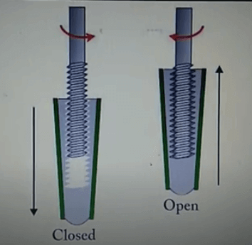
non-rising stem gate valve-open and close position
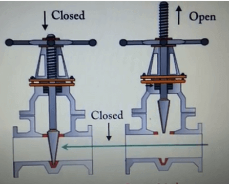
rising stem gate valve-open and closed position
Classification by other methods:
According to different standards: national standard gate valve, American standard gate valve, German standard gate valve, Japanese standard gate valve
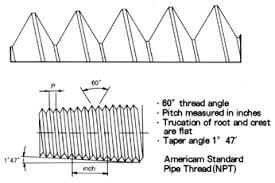
According to the connection method: flange gate valve, welded gate valve, threaded gate valve (divided into internal thread and external thread)
According to pressure level: high pressure gate valve, low (medium) pressure gate valve
According to the driving mode: electric gate valve, pneumatic gate valve, manual gate valve
Classified by material: stainless steel gate valve, forged steel gate valve, cast steel gate valve, carbon steel gate valve, cast iron gate valve, copper gate valve (also divided into bronze gate valve, brass gate valve), ceramic gate valve, plastic gate valve
The main difference:
1. The lifting screw of the concealed rod flange gate valve only rotates and moves up and down. Only a rod is exposed. The screw cap is fixed on the disc. The disc is raised by the rotation of the screw, and there is no visible electric gate valve frame. ; The lifting screw of the rising stem flange gate valve is exposed, and the screw cap is close to the hand wheel and is fixed (not high-pressure gate valve rotation nor axial movement), the disc is improved by rotating the screw, the screw and the disc have only relative rotational movement There is no relative axial displacement, and the appearance is a gate-shaped bracket.
2. The valve stem with dark stem cannot be seen, while the stem with open stem can be seen.
3. The steering wheel and the valve stem are connected and relatively immovable when the dark stem valve is opened and closed. The valve stem rotates at a fixed point to help the valve clack move upward and downward to complete the opening and closing. The rising stem valve is driven by the turnbuckle of the valve stem and the steering wheel to raise or lower the disc.
To put it simply, the rising stem valve is that the disc and the stem move up and down together, and the steering wheel is always at a fixed point.
Is rising-stem gate valve or non rising-stem gate valve used outdoors?
For the valves installed in the outdoor valve wells, according to the experience of Tanghai valves, it is recommended that you use dark stem valves. The use of rising stem valves has the following disadvantages: 1. When the valve is opened and closed, the valve stem has to rise and fall, which takes up a lot of space. If the pipeline is not buried very deep, the valve well will hinder the opening of the valve. When the valve is opened, the valve well cover will not be closed or the valve cannot be fully opened. 2. After the number of switches is increased, the contact surface of the valve stem and the pressure flange will leak more seriously, and the packing should be replaced frequently. 3. If you don’t switch frequently, a part of the valve stem will be exposed to the valve body for a long time. In the humid environment of the valve well, the exposed valve stem is very easy to oxidize and rust. Once it needs to be closed, it will not be closed. Otherwise, grease must be applied frequently. In short, the maintenance workload is large. Dark stem valves do not have these problems, the probability of water leakage is also small, and of course the maintenance workload is also small. for reference only.
The opening and closing part of the rising-stem gate valve (gate valve) is a disc, and the movement direction of the disc is perpendicular to the direction of the fluid. The rising-stem gate valve can only be fully opened and fully closed, and cannot be adjusted or throttled.
Disc has two sealing surfaces. The two sealing surfaces of the most commonly used mode disc valve form a wedge. The wedge angle varies with valve parameters, usually 50, and 2°52′ when the medium temperature is not high. The disc of the wedge gate valve can be made into a whole, called a rigid disc; it can also be made into a disc that can produce slight deformation to improve its manufacturability and make up for the deviation of the sealing surface angle during the processing. This disc is called an elastic disc .
The types of rising-stem gate valve can be divided into wedge disc gate valve and parallel disc gate valve according to the sealing surface configuration. Wedge disc gate valve can be divided into: single disc type, double disc type and elastic disc type; parallel disc Type gate valve can be divided into single disc type and double disc type. According to the thread position of the valve stem, it can be divided into rising-stem gate valve and non rising-stem gate valve.
When the rising-stem gate valve is closed, the sealing surface can only rely on the medium pressure to seal, that is, only rely on the medium pressure to press the sealing surface of the disc to the valve seat on the other side to ensure the sealing of the sealing surface, which is self-sealing. Most gate valves adopt forced sealing, that is, when the valve is closed, the disc must be forced to the valve seat by external force to ensure the tightness of the sealing surface.
The working principle of rising-stem gate valve
Rotate the hand wheel, through the advance and retreat of the thread of the hand wheel and the valve stem, raise or lower the valve plate connected with the valve stem to open and close
The rising-stem gate valve has the following advantages:
The fluid resistance is small, and the sealing surface is less eroded and eroded by the medium.
It is easier to open and close.
The flow direction of the medium is not restricted, does not disturb the flow, and does not reduce the pressure.
The shape is simple, the length of the structure is short, the manufacturing process is good, and the scope of application is wide.
The disadvantages of rising-stem gate valve are as follows:
It is easy to cause erosion and scratches between the sealing surfaces, and maintenance is difficult.
The overall size is large, opening requires a certain amount of space, and the opening and closing time is long.
The structure is more complicated.
The types of gate valves can be divided into wedge disc gate valves and parallel disc gate valves according to the sealing surface configuration. Wedge disc gate valves can be further divided into: single gate, double disc and elastic disc; parallel disc gate valves can be Divided into single disc type and double disc type. According to the thread position of the valve stem, it can be divided into rising-stem gate valve and non rising-stem gate valve.
Installation and maintenance of rising-stem gate valve:
Handwheels, handles and transmission mechanisms are not allowed to be used for lifting, and collisions are strictly prohibited.
The double disc gate valve should be installed vertically (that is, the valve stem is in the vertical position and the handwheel is at the top).
The gate valve with a bypass valve should be opened before opening (to balance the pressure difference between the inlet and outlet and reduce the opening force).
The gate valve with transmission mechanism should be installed according to the product manual.
If the valve is frequently opened and closed, lubricate at least once a month.
Structural characteristics of rising-stem gate valve:
The general gate valves used on the market for a long time generally have water leakage or rust. The company introduces the elastic seat seal gate valve produced by European high-tech rubber and valve manufacturing technology, which overcomes the defects of poor sealing and rust of general gate valves. The sealing gate valve uses the compensation effect of the elastic disc to produce a small amount of elastic deformation to achieve a good sealing effect. The valve has the obvious advantages of light switch, reliable sealing, good elastic memory and service life. It can be widely used as a regulating and intercepting device on the pipelines of tap water, sewage, construction, petroleum, chemical industry, food, medicine, textile, electric power, shipbuilding, metallurgy, energy system, etc.
Features of rising-stem gate valve:
Light weight: The body is made of high-grade ductile iron, which is about 20% to 30% lighter than the traditional gate valve, and is easy to install and maintain.
Flat-bottomed gate seat: The traditional gate valve often deposits in the groove at the bottom of the valve due to foreign objects such as stones, wood, cement, iron filings, and other debris after the pipe is washed with water. The bottom of the elastic seat-sealed gate valve adopts the same flat-bottom design as the water pipe machine, which is not easy to cause debris siltation and makes the fluid flow unimpeded.
Integral encapsulation: The disc adopts high-quality rubber for the overall inner and outer rubber. European first-class rubber vulcanization technology enables the vulcanized disc to ensure accurate geometric dimensions, and the rubber and ductile disc are connected firmly, not easy to fall off, and have good elastic memory . water
Precision casting valve body: The valve body adopts precision casting, and the precise geometric dimensions make the inside of the valve body without any finishing to ensure the sealing of the valve.
Features of dark-rod soft-seal gate valve:
The overall valve encapsulation is used to produce a deformation compensation effect to achieve a good sealing effect, overcome the poor sealing, water leakage and rust of the general gate valve, and save installation space more effectively. It can be widely used in tap water, sewage, construction, petroleum, chemical, It is used as a regulating and intercepting device on fluid pipelines such as food, medicine, textile, electric power, shipbuilding, metallurgy, energy systems. Our factory introduces European high-tech valve manufacturing technology to produce elastic seat-sealed gate valves, which are deformed by the overall encapsulation of the gate. The compensation effect achieves a good sealing effect and overcomes the phenomenon of poor sealing, water leakage and rust of general gate valves. It can be widely used as a regulating and intercepting device on fluid pipelines such as tap water, sewage, construction, petroleum, chemical industry, food, medicine, minor injuries, electric power, ships, metallurgy, and energy systems.
1. The gate adopts integral rubber encapsulation, and its good covering performance and precise geometric dimensions ensure reliable sealing and longevity.
2. Light weight: The valve body is made of ductile iron, which is light in weight and easy to install.
3. Flat-bottomed valve seat: The bottom is designed with the same flat-bottomed valve seat as the water pipe, which does not produce debris and makes the seal more reliable.
4. Corrosion resistance: The inner cavity is coated with non-toxic epoxy resin to prevent corrosion and rust. Not only can it be used for raw drinking, but also can be used in sewage systems.
5. Three “0” seal: The valve stem is sealed with three O-rings, with low friction resistance, light switch and no water leakage.
How to select the non rising-stem gate valve and rising-stem gate valve?
For oil and natural gas pipelines, single disc or double disc gate valves are used. If you need to clean the pipeline, use a single disc or double disc rising-stem gate valve with diversion holes.
For the transportation pipeline and storage equipment of refined oil, select single disc or double disc gate valve without diversion hole.
For oil and natural gas mining wellhead devices, single disc or double disc gate valves with dark rod floating valve seats and diversion holes are selected, most of which are API16A standards, and the pressure levels are API2000, API3000, API5000, API10000, API15000, API20000.
For pipelines with suspended particulate media, use knife-shaped plate gate valves.
The city gas transmission pipeline adopts single disc or double disc soft-sealed rising-stem gate valve.
For urban tap water projects, single disc or double disc rising-stem gate valve without diversion hole is used.