Comparison table of valve diameter and medium flow rate
It is well known that the flow rate and flow rate of the valve mainly depend on the diameter of the valve, and also

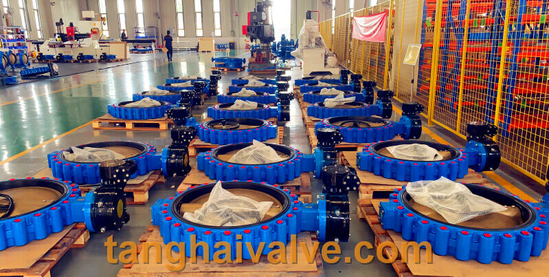
ductile iron, DI, butterfly valve, manufacturer, center line, TH valve
related to the resistance of the valve structure to the medium. At the same time, it has a certain internal connection with various factors such as the valve pressure, temperature and medium concentration. The flow channel area of the valve has a direct relationship with the flow rate and flow rate, and the flow rate and flow rate are two mutually dependent quantities. When the flow rate is constant, the flow rate is large, the flow channel area can be smaller; the flow rate is small, the flow channel area can be larger. On the contrary, the flow channel area is large, its flow velocity is small; the flow channel area is small, its flow velocity is large.
1. The flow rate of the medium is large, and the valve diameter can be smaller, but the resistance loss is large and the valve is easily damaged. If the flow velocity is large, it will have electrostatic effect on flammable and explosive media, causing danger; the flow velocity is too small, the efficiency is low and it is not economical. For the medium with high viscosity and explosive, the flow rate should be smaller. The flow rate of oil and liquid with high viscosity is selected according to the viscosity, generally 0.1~2m/s.
2. In general, the flow rate is known, and the flow rate can be determined by experience. The nominal diameter of the valve can be calculated through the flow rate and flow rate.
3. The valve diameter is the same, its structure type is different, and the fluid resistance is also different. Under the same conditions, the larger the resistance coefficient of the valve, the more the flow rate and flow rate of the fluid through the valve will drop; the smaller the valve resistance coefficient, the less the flow rate and flow rate of the fluid through the valve will drop.
The common flow rates of various media are shown in the following table:
| liquid type | use condition | speed m/s |
| satuated vapor | DN>200 | 30-40 |
| DN=200-100 | 25-35 | |
| DN<100 | 15-30 | |
| superheated steam | DN>200 | 40-60 |
| DN=200-100 | 30-50 | |
| DN<100 | 20-40 | |
| low pressure steam | P<1.0 (absolute pressure) | 15-20 |
| midium pressure steam | P=1.0-4.0 (absolute pressure) | 20-40 |
| high pressure steam | P=4.0-12.0 (absolute pressure) | 40-60 |
| compressed air | vaccum | 5-10 |
| P≤0.3 (instrument pressure) | 8-12 | |
| P=0.3-0.6 (instrument pressure) | 10-20 | |
| P=0.6-1.0 (instrument pressure) | 10-15 | |
| P=1.0-2.- (instrument pressure) | 8-12 | |
| P=2.0-3.0 (instrument pressure) | 3-6 | |
| P=3.0-30.0 (instrument pressure) | 0.5-3 | |
| Oxygen | P=0-0.05 (instrument pressure) | 5-10 |
| P=0.05-0.6 (instrument pressure) | 7-8 | |
| P=0.6-1.0 (instrument pressure) | 4-6 | |
| P=1.0-2.0 (instrument pressure) | 4-5 | |
| P=2.0-3.0 (instrument pressure) | 3-4 | |
| gas | 2.5-15 | |
| semi-water gas | P=0.1-0.15 (instrument pressure) | 10-15 |
| natural gas | 30 | |
| Nitrogen | P=5.0-10.0 (absolute pressure) | 15-25 |
| Ammonia | vaccum | 15-25 |
| P<0.3 (instrument pressure) | 8-15 | |
| P<0.6 (instrument pressure) | 10-20 | |
| P≤2 (instrument pressure) | 3-8 | |
| Acetylene water | 30 | |
| 5-6 | ||
| Acetylene gas | P<0.01 (instrument pressure) | 3-4 |
| P<0.15 (instrument pressure) | 4-8 | |
| P<0.25 (instrument pressure) | 5 | |
| chlorine | gas | 10-25 |
| liquid | 1.6 | |
| Hydrogen chloride | gas | 20 |
| liquid | 1.5 | |
| liquid ammonia | vaccum | 0.05-0.3 |
| P≤0.6 (instrument pressure) | 0.3-0.8 | |
| P≤2.0 (instrument pressure) | 0.8-1.5 | |
| Sodium hydroxide | concentration 0-30% | 2 |
| concentration 30-50% | 1.5 | |
| concentration 50-73% | 1.2 | |
| Sulfuric acid | concentration 88-93% | 1.2 |
| concentration 93-100% | 1.2 | |
| hydrochloric acid | 1.5 | |
| water and other similar viscosity liquid | P=0.1-0.3 (instrument pressure) | 0.5-2 |
| P≤1.0 (instrument pressure) | 0.5-3 | |
| P≤8.0 (instrument pressure) | 2-3 | |
| P≤20-30 (instrument pressure) | 2-3.5 | |
| Heating network circulating water Cooling water | 0.3-1 | |
| pressure backwater | 0.5-2 | |
| pressureless backwater | 0.5-1.2 | |
| tap water | main pipe P=0.3 (instrument pressure) | 1.5-3.5 |
| sub pipe P=0.3 (instrument pressure) | 1-1.5 | |
| boiler feed water | >3 | |
| steam condensate | 0.5-1.5 | |
| condensate | free flow | 0.2-0.5 |
| superheated water | 2 | |
| seawater and brackish water | P<0.6 (instrument pressure) | 1.5-2.5 |
Note: The unit of DN value is mm; the unit of P value is MPa.
for example:
The resistance coefficient of the gate valve is small, only in the range of 0.1 to 1.5; the resistance coefficient of the large diameter gate valve is 0.2 to 0.5; the resistance coefficient of the narrow gate valve is larger.
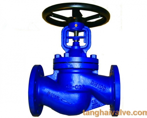
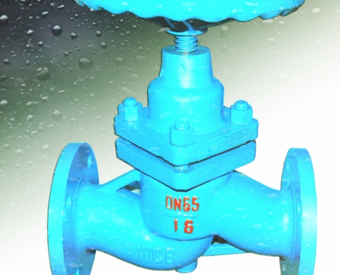
The resistance coefficient of the stop valve is much larger than that of the gate valve, generally between 4 and 7.
The resistance coefficient of the Y-type globe valve (DC type) is small, between 1.5 and 2; the resistance coefficient of the forged steel globe valve is large, even as high as 8.
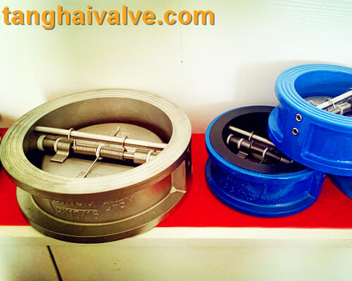
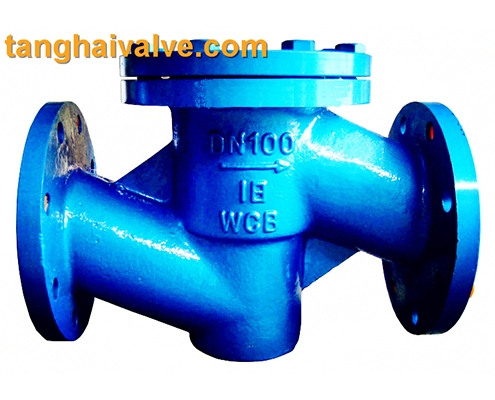
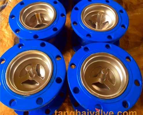
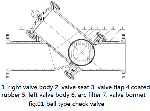
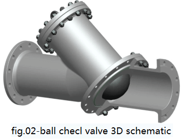
The resistance coefficient of the check valve depends on the structure: the swing check valve is usually about 0.8-2, among which the multi-leaf swing check valve has a large resistance coefficient; the lift check valve has a large resistance coefficient, up to 12 .
The resistance coefficient of the plug valve is small, usually about 0.4 to 1.2.
The resistance coefficient of the diaphragm valve is generally around 2.3.
The drag coefficient of butterfly valve is small, generally within 0.5. The resistance coefficient of the ball valve is small, generally around 0.1.
Note: The resistance coefficient of the above valve is the value when the valve is fully opened. The selection of valve diameter should take into account the machining accuracy and dimensional deviation of the valve, as well as other factors. The valve diameter should have a certain margin, generally 15%. In actual work, the valve diameter depends on the diameter of the process pipeline.
Related products: wafer butterfly valve; lug butterfly valve; double flange butterfly valve;
Double eccentric butterfly valve
TH Valve is a professional manufacturer of butterfly valve, gate valve, check valve, globe valve, knife gate valve, ball valve with API, JIS, DIN standard, used in Oil, Gas, Marine industry, Water supply and drainage, fire fighting, shipbuilding, water treatment and other systems, with Nominal Diameter of DN50 to DN1200, NBR/EPDM/VITON, Certificates & Approvals: DNV-GL, Lloyds, DNV, BV, API, ABS, CCS. Standards: EN 593, API609, API6D
Related news/knowledge:
Prevention and treatment of valve corrosion;
Valve flow characteristic curve and classification;
What is the gear modification coefficient;
Valve model establishment and meaning