Working principle diagram of swing check valve
Working principle diagram of swing check valve
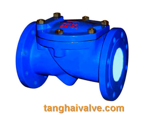
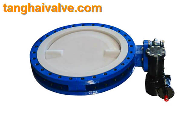
Swing check valve, also known as check (flow) valve, is an automatic valve used on one-way flow pipelines to prevent the medium from flowing back. It depends on the pressure of the pipeline medium to open or close the valve. It can be divided into single valve type , Double valve type and multi valve type, are one of the more commonly used valves. Swing check valves are generally suitable for pipelines with relatively clean fluid media. They are not suitable for
swing-check-valve-working-principle-diagram
working conditions with high viscosity or solid particles. Otherwise, the check valve will be insensitive to opening and cannot achieve a complete seal. The answer is not reliable enough. The swing check valve only allows the medium to flow in one direction, which can effectively prevent the medium from flowing back to prevent accidents.
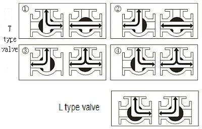
The working principle of the swing check valve:
The disc of the swing check valve and the rocker are connected together, and can rotate a certain angle around the pin shaft. When the pipeline fluid flows in the specified direction (from left to right), the inlet pressure of the disc is higher than the outlet pressure. At this time, the disc is pushed away from the valve seat and rotates around the pin to a certain position, and the valve is in the open state. When the pressure difference between the two sides of the valve flap decreases to a certain level, the valve flap falls and returns to the closed state. When the fluid flows from right to left, that is, reverse flow, the pressure on the right side of the valve disc is higher than the pressure on the left side, and the force generated by the pressure difference on both sides presses the valve disc on the valve seat, and the fluid cannot pass through, the medium Can not flow back; and the greater the fluid pressure, the tighter the sealing surface is, and the better the sealing effect. To
The installation position of the swing check valve is not restricted. It can be installed horizontally in the pipeline, or on a vertical or inclined pipeline, but if it is installed on a vertical pipeline, the flow direction of the medium should be from bottom to top.
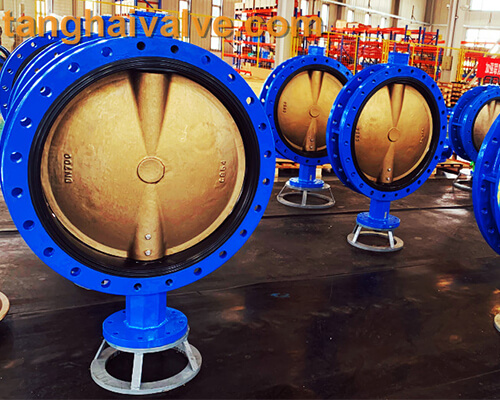
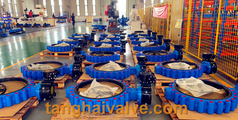
TH Valve is a professional manufacturer of butterfly valve, gate valve, check valve, globe valve, knife gate valve, ball valve with API, JIS, DIN standard, used in Oil, Gas, Marine industry, Water supply and drainage, fire fighting, shipbuilding, water treatment and other systems, with Nominal Diameter of DN50 to DN1200, NBR/EPDM/VITON, Certificates & Approvals: DNV-GL, Lloyds, DNV, BV, API, ABS, CCS. Standards: EN 593, API609, API6D
Related news/knowledge:
Basic knowledge of valve;
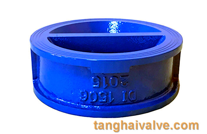
What is double plate swing check valve;
Butterfly valve use principle and installation instructions;
Wafer type double disc swing check valve introduction