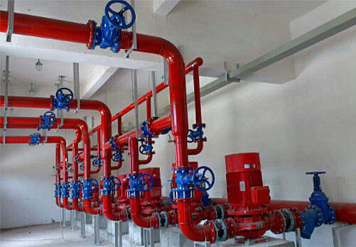
What are the commonly used valves
The valve is a pipeline accessory, used to open and close the pipeline and control the flow of fluid medium in the pipeline. The functions of the valve in the pipeline include cut-off, regulation, diversion, prevention of reverse flow, stabilization, diversion or overflow and pressure relief. There are many types of valves. As the control components of fluid control systems, from the simplest butterfly valves and gate valves to the various valves used in extremely complex automatic control systems, there are many varieties and specifications.

ductile iron, DI, butterfly valve, manufacturer, center line, TH valve
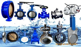
Valves can be used to control the flow of various types of fluids, such as air, water, steam, various corrosive media, mud, oil, liquid metal, and radioactive media. The application range covers various industries. Although there are many types of valves, what are the commonly used valves? This article introduces you one by one:
There are five types of commonly used valves: butterfly valves, gate valves, check valves, ball valves, and stop valves.
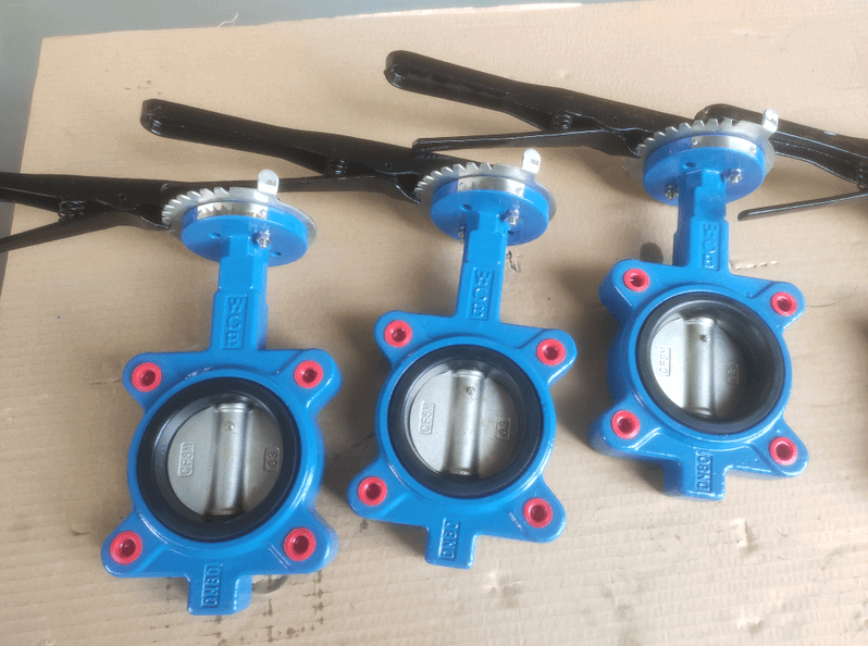
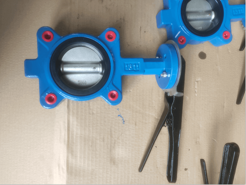
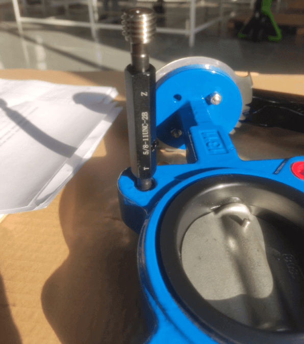
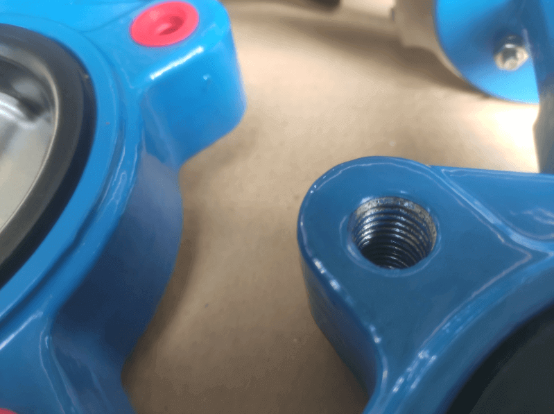
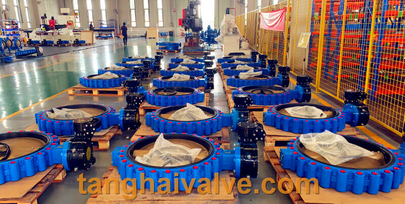
Butterfly valve:
The butterfly valve, also known as the flap valve, is a simple and easy-to-use regulating valve. The butterfly plate in the body of the butterfly valve is the closing part of the valve, which is in the shape of a disc. The working principle is that the butterfly plate rotates around the valve shaft to realize the valve. Open and close, usually, the butterfly plate is driven by the valve stem and rotates 90° to complete one opening and closing, and achieve the purpose of interception. If you change the deflection angle of the butterfly plate, it can also be used as a flow control. Under normal circumstances, butterfly valves are often used for on-off control of low-pressure pipeline media.
Wafer butterfly valve and flange butterfly valve are the two connection forms of butterfly valve. The butterfly valve is suitable for making large-diameter valves, suitable for natural gas, liquefied petroleum gas, city gas, cold and hot air, chemical smelting and power generation, environmental protection, building water supply and drainage, etc. It is used to regulate and cut off the flow of media on the pipelines that transport various corrosive and non-corrosive fluid media in the system.
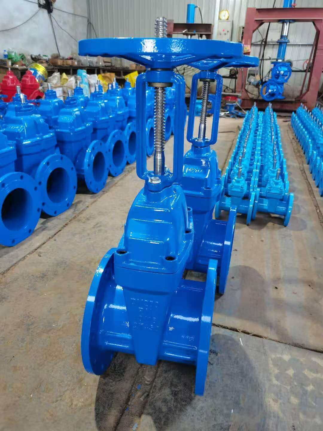
gate valve:
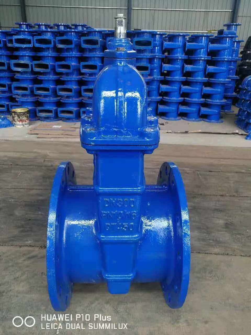
non-rising-stem-gate-valve-IS&Y
Gate valves are usually used for interception in pipeline systems. Its opening and closing parts are gates. The movement direction of the gate is perpendicular to the direction of the medium flow in the pipeline. The gate rises and the valve opens to realize the flow of the pipeline medium; the gate falls, The valve is closed, and the flow of the pipeline medium is cut off. The gate valve can only be fully opened or fully closed to cut off the flow of the medium, and cannot be used for adjustment and throttling. Therefore, the gate valve is generally used to keep the gate valve gate plate fully open and fully closed, and is used in a pipeline environment that does not need to be opened and closed frequently.
According to the structure of the gate, the gate valve can be divided into two types: wedge gate valve and parallel gate valve. Wedge gate valves can be divided into three types: single gate valve, double gate valve and elastic gate valve.
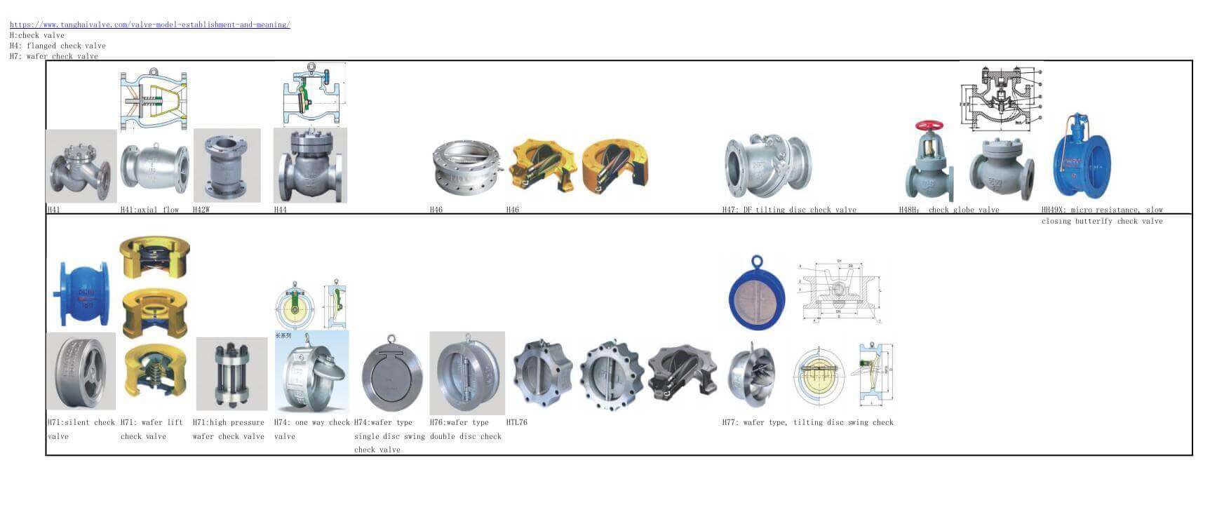
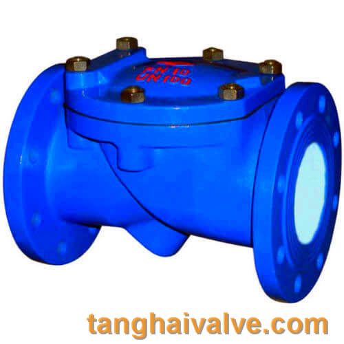
Check valve:
The check valve is also a list valve or check valve, which is an automatic valve, which
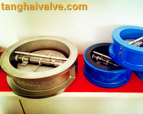
double-wing-check-valve-3
means that the check valve works automatically and does not require manual operation. When the medium flows through the check valve, under the pressure impact of the fluid medium, the check valve The valve flap of the return valve opens automatically and the medium passes through; after the medium flow is cut off, the valve flap automatically closes under the force of its own spring device to prevent the medium from flowing back and backflow.
Check valves are only suitable for installation in pipelines where the medium flows in one direction. The main function is to prevent the medium from flowing backwards, to prevent the pump and drive motor from reversing, and to discharge the container medium.
Globe valve:
The globe valve, also known as the shut-off valve, is a forced-sealing valve. That is to say, unlike the automatic operation of a check valve, the shut-off valve must apply pressure to the disc when it is closed to force the sealing
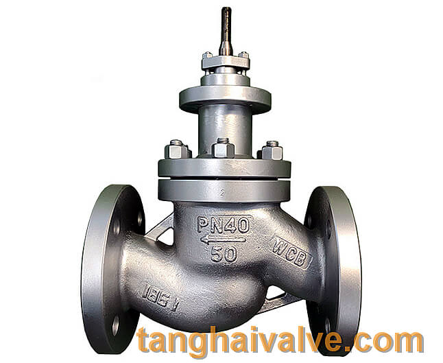
globe valve body
surface to not leak. When the medium enters the valve from below the disc, the flow direction changes, so the resistance that needs to be overcome to close the shut-off valve is the friction between the valve stem and the packing, as well as the thrust generated by the pressure of the medium, and the force to close the valve. The force is larger than that of opening the valve, so the diameter of the valve stem should be larger, otherwise the valve stem will bend failure. The flow resistance of the stop valve is higher than other valves.
The shut-off valve can be used to cut off the medium like a gate valve, but more often, people use the shut-off valve to adjust the flow.
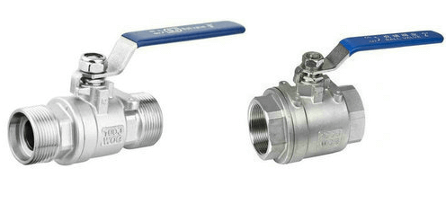
Ball valve:
The ball valve evolved from the rotary valve. It is the same as the butterfly valve in that it also needs to be rotated 90 degrees to open and close. The difference is that the butterfly
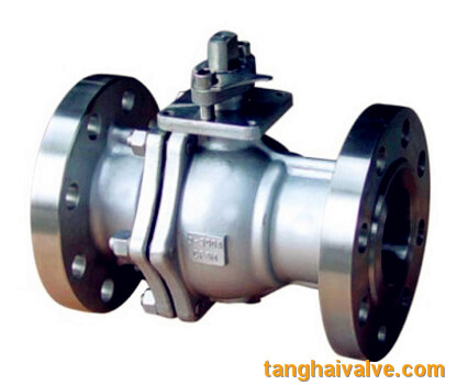
ball valve (8)
valve is a butterfly plate, and the cock of the ball valve is a sphere, with a circular through hole or channel passing through its axis.
The ball valve can cut off, distribute and change the flow direction of the medium in the pipeline, and only need to rotate 90 degrees and a small torque can be closed tightly. Therefore, the ball valve is most suitable for use as a switch and shut-off valve. At present, it has been widely used in petroleum refining, long-distance pipeline, chemical industry, papermaking and other industries.
TH Valve is a professional manufacturer of butterfly valve, gate valve, check valve, globe valve, knife gate valve, ball valve with API, JIS, DIN standard, used in Oil, Gas, Marine industry, Water supply and drainage, fire fighting, shipbuilding, water treatment and other systems, with Nominal Diameter of DN50 to DN1200, NBR/EPDM/VITON, Certificates & Approvals: DNV-GL, Lloyds, DNV, BV, API, ABS, CCS. Standards: EN 593, API609, API6D
Related news/knowledge:
O type |V type ball valve structure principle;
The difference between globe valve and check valve;
The working principle and characteristics of the globe valve;
Electric globe valve selection and application