Tag Archive for: valve

Posts

Classification and introduction of pipe thread-(2)

“Cylinder/cone” and “cone/cone”. Two inch seal pipe threads use different thread ring gauges (cylindrical thread ring gauge and tapered thread ring gauge) and thread plug gauge (the position of the datum plane is different, the two datum planes are different Half-tooth apart). Pipe threads that pass the inspection in European countries may be unqualified if they are inspected by countries outside of Europe. In international trade, you must pay attention to this difference, otherwise there may be waste. Before 1994, the ISO standard for sealed pipe threads and their gauges The standard is designed according to the “cone/cone” coordination system. China’s imperial sealed pipe thread products can directly enter the international market. However, the pipe thread products of European countries are in a disadvantageous position. After 2000, ISO’s imperial seal The pipe thread standard and its gauge standard are designed according to the “column/cone” matching question system. Our country’s original inch seal pipe thread products will encounter difficulties when entering the international market. For this reason, China revised the inch seal pipe in 2000 Thread national standard. Change the original one thread standard into two thread standards to remind the designer to pay attention to the difference and correct selection of the two mating threads. Japan still insisted on adopting 1994 when it revised the inch seal pipe thread standard in 1999 The ISO standard a year ago. Therefore, the international inch seal pipe thread market after 2000 is more complicated, and domestic

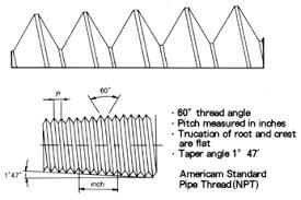
NPT thread picture

NPT thread picture

manufacturers must be careful.

Inch sealing pipe thread is a general purpose sealing pipe thread. Sealing filler should be added to the thread pair during use. Its characteristics are economical and the processing accuracy requirements are moderate. Without sealing fillers, it can ensure that the sealed connection thread is dry sealed Pipe thread. There is no dry seal pipe thread in the inch pipe thread system.

Sealed pipe threads have two functions: mechanical connection and sealing; non-sealed pipe threads have only one function of mechanical connection. Therefore, the accuracy of sealed pipe threads is stricter than that of unsealed pipe threads. Some people see unsealed pipe threads The tolerance of the pitch diameter is half of the tolerance of the sealed pipe thread. It is considered that the accuracy of the unsealed pipe thread is higher than that of the sealed pipe thread. This view is incorrect. The sealed pipe thread has requirements for the accuracy of the tooth shape. Its large diameter, The tolerances of the pitch diameter and the minor diameter are the same; the flank angle and pitch error have a greater impact on the sealing performance. The non-sealed pipe thread basically has no requirements for the accuracy of the tooth form. The top diameter tolerance is greater than the pitch diameter tolerance; the bottom diameter There is no tolerance requirement. In addition, some people think that it is possible to use non-sealed cylindrical internal threads and sealed cylindrical external threads to form a fit. This view is also wrong. This is equivalent to relaxing the accuracy requirements of sealed internal threads, and the sealing of pipe threads There may be a problem.

Due to differences in the use of sealed pipe threads, processing accuracy, assembly and testing techniques, the pipe thread standard cannot guarantee that all threaded parts that meet the standard can be sealed. In the imperial sealed pipe thread standard, a unified thread item cannot be proposed. The accuracy requirements of the parameters. These individual thread parameters have a direct impact on the sealing performance. The fundamental way to solve the problem is to formulate their own internal control measures for their specific products. Each industry or company formulates its own internal control measures. The internal control indicators of these parameters are generally confidential. Companies in other industries are not universal, and manufacturers must have a clear understanding of this. Sealing pipe thread standards are not omnipotent, and sealing problems may require manufacturers to pay attention to them. Before 1987, China did not have American and British pipe thread standards. But In production, these two internationally commonly used pipe thread standards cannot be avoided. For this reason, the old mechanical drawing standards once stipulated the marking codes for American and British pipe threads. These thread codes are derived from the Chinese Pinyin alphabet, and have not considered the foreign Whether the standard codes of standard pipe threads are consistent. Since this standard only specifies the thread codes and not the thread parameters, the same thread code may have different thread parameters in different companies or industries. There is no basis for judging who is right and who is wrong when there is a scrap .From 1987 to 1991, China promulgated the British pipe thread standard. From then on, the pipe thread code and marking should comply with the pipe thread standard. The pipe thread code specified in the old mechanical drawing standard should be abolished immediately.

Classification and introduction of pipe thread-(1)

Pipe thread is a thread used for connection on the pipe wall to the valves. There are 55-degree unsealed pipe threads and 55-degree sealed pipe threads. Mainly used to connect pipes to make the internal and external threads fit tightly. There are two types which are straight pipes thread and tapered pipes thread.
Common pipe threads mainly include the following types: NPT, PT, G, etc.

NPT thread picture

NPT thread picture

1) NPT is the abbreviation of National (American) Pipe Thread, which belongs to the American standard 60-degree tapered pipe thread and is used in North America. Refer to GB/T12716-1991 for the national standard.

2) PT (BSPT) is the abbreviation of Pipe Thread. It is a 55-degree sealed tapered pipe thread. It belongs to the Wyeth thread family. It is mostly used in Europe and the Commonwealth countries. It is often used in the water and gas pipe industry. The taper is 1:16. Refer to GB/ T7306-2000. The domestic name is ZG.

3) G is a 55-degree non-sealed pipe thread, which belongs to the Wyeth thread family. Marked as G stands for cylindrical thread. Refer to GB/T7307-2001 for the national standard.

Metric and inch threads

Metric threads are expressed by pitch, while American and British threads are expressed by the number of threads per inch;

Metric thread is 60-degree equilateral profile, inch thread is isosceles 55-degree profile, and American thread is isosceles 60-degree profile;

Use metric units (such as mm) for metric threads, and use imperial units (such as inches) for American and British threads;

“Insiders” usually use “minutes” to refer to the thread size, one inch equals 8 points, 1/4 inch equals 2 points, and so on.

In addition, there are: ISO—Metric Thread Standard 60°; UN—Unified Thread Standard 60°; API—American Petroleum Pipe Thread Standard 60°; W—British Wyeth Thread Standard 55°.

The difference between various threads

NPT, PT, G  are all pipe threads.

NPT is the abbreviation of National (American) Pipe Thread, which belongs to the American standard 60-degree tapered pipe thread and is used in North America. National standards can be found in GB/T12716-1991

PT is the abbreviation of Pipe Thread. It is a 55-degree sealed tapered pipe thread. It belongs to the Wyeth thread family and is mostly used in Europe and Commonwealth countries. Commonly used in water and gas pipe industry, the taper is 1:16. National standards can be found in GB/T7306-2000

G is a 55-degree non-thread sealed pipe thread, which belongs to the Wyeth thread family. Marked as G stands for cylindrical thread. National standards can be found in GB/T7307-2001

In addition, the 1/4, 1/2, and 1/8 marks in the thread refer to the diameter of the thread size, and the unit is inch. Insiders usually use points to refer to the thread size, one inch equals 8 points, 1/4 inch equals 2 points, and so on. G is the general name of pipe thread (Guan). The division of 55 and 60 degrees is functional, commonly known as pipe circle. That is, the thread is processed by a cylindrical surface.

ZG is commonly known as pipe cone, that is, the thread is processed by a conical surface. The general water pipe joints are like this. The national standard is marked as Rc metric thread to indicate the pitch, and the American thread is 60 degrees. Metric units are used for metric threads, and imperial units are used for American and British threads. Pipe thread is mainly used to connect pipelines. The internal and external threads are closely matched. There are two types of straight pipes and tapered pipes. The nominal diameter refers to the diameter of the connected pipe, obviously the thread diameter is larger than the nominal diameter. 1/4, 1/2, 1/8 are the nominal diameters of inch threads, and the unit is inches.

Inch pipe threads are derived from British Wyeth threads. The combination of Wyeth threaded pipe series and Wyeth thread profiles establishes the basic dimensions of British pipe threads. According to the 1/16 taper relationship, the radial diameter tolerance of Wyeth threads is converted into British sealed tubes. Tolerance of the axial number of threads (there is a certain amount of rounding and adjustment). Then refer to the tolerance value of the inch seal pipe thread to propose the tolerance of the inch unsealed pipe thread (the tolerance changes from one-way distribution to one-way distribution, relax the top Diameter tolerance, let go of the bottom diameter tolerance). The time for the three types of threads is:

In 1841, the British Wyeth thread was proposed, and in 1905, the new Wyeth thread standard (BS 84) was promulgated.

In 1905, the British Sealed Pipe Thread Standard (BS 21) was promulgated.

From 1905 to 1940, Wyeth Thread performed the responsibility of the imperial unsealed pipe. In 1940, the unsealed pipe thread series (BSP series) of Wyeth Thread was proposed; in 1956, the British unsealed pipe thread standard (BS 2779) was issued separately.

European countries and Commonwealth countries first accepted the imperial pipe thread standard. The ISO/TC5/SC5 Pipe Thread Standardization Technical Committee and its secretariat are controlled by European countries, and the imperial pipe thread standard was adopted by the ISO standard. In 1955, the ISO proposed the imperial sealed pipe thread Standard (ISO R 7); In 1961, ISO proposed the standard for imperial unsealed pipe threads (ISO R 228). In 1978, ISO promulgated two official standards for imperial pipe threads (ISO7-1 and ISO228-1). Threads have been generally accepted by countries outside North America and are widely used in international trade.

The inch pipe thread in the ISO standard has been converted to the metric system. The metric method of the inch pipe thread is very simple. Multiply the inch size of the original pipe thread by 25.4 to convert it to the millimeter size. The inch pipe thread size is being eliminated. The so-called use of real pipe thread standards is unrealistic. There is no distinction between real metric pipe threads and fake metric pipe threads.

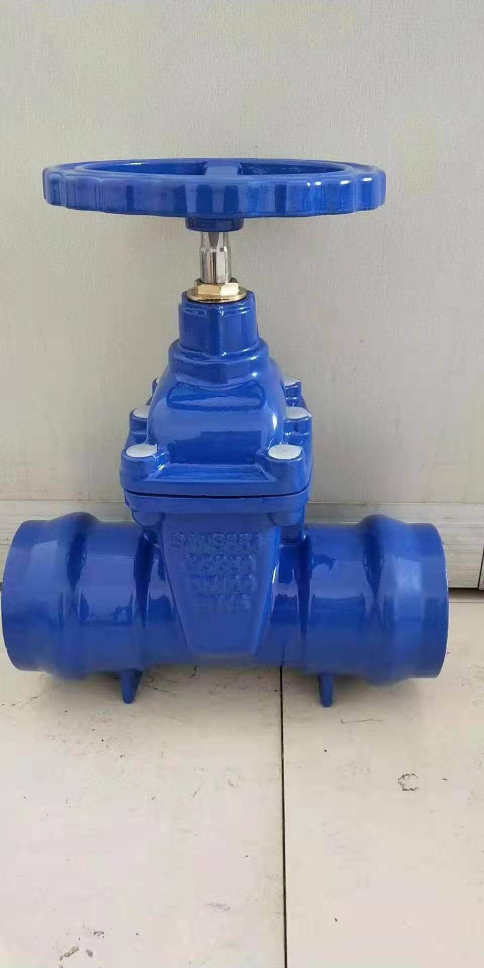
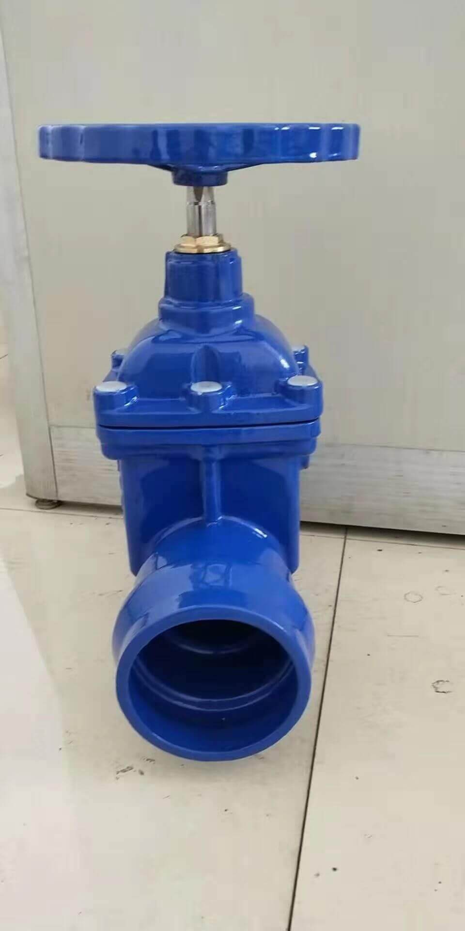
Resilient seated socket end gate valve

GATE VALVE-resilient seated SOCKET END
Standard: EN1074; EN1171

Socket ended resilient seated wedge gate valve-ductile iron (1)

Socket ended resilient seated wedge gate valve-ductile iron (1)

CAST IRON / DUCTILE IRON GATE VALVE SOCKET END
NON RISING STEM
Pressure: PN10 / PN16
Connection ends: Socked ends, for PVC pipes, uPVC pipes
FACE TO FACE: ACCORDING TO BS, DIN, ANSI, AWWA, SABS STANDARD ETC.
BODY:CAST IRON/DUCTILE IRON
BONNET:CAST IRON/DUCTILE IRON
WEDGE:CAST IRON/DUCTILE IRON, fully vulcanized with EPDM rubber
STEM: SS/BRASS
Coating: fusion bonded expoxy coating

The opening and closing part of the socket gate valve is a gate. The movement direction of the gate is perpendicular to the direction of the fluid. The gate valve can only be fully opened and fully closed, and cannot be adjusted or throttled. The gate has two sealing surfaces. The two sealing surfaces of the most commonly used mode gate valve form a wedge. The wedge angle varies with valve parameters, usually 50, and 2°52′ when the medium temperature is not high. The gate of the wedge gate valve can be made into a whole, called a rigid gate; it can also be made into a gate that can produce slight deformation to improve its manufacturability and compensate for the deviation of the sealing surface angle during the processing. The plate is called an elastic gate.

Socket gate valve can be divided into wedge gate valve and parallel gate valve according to the sealing surface configuration. The wedge gate valve can be divided into: single gate, double gate and elastic gate; parallel gate valve can be divided into It is single gate type and double gate type. According to the thread position of the valve stem, it can be divided into two types: rising stem gate valve and non-rising stem gate valve.

When the socket gate valve is closed, the sealing surface can only rely on the medium pressure to seal, that is, rely on the medium pressure to press the sealing surface of the gate against the valve seat on the other side to ensure the sealing of the sealing surface, which is self-sealing. Most gate valves use forced sealing, that is, when the valve is closed, the gate must be forced against the seat by external force to ensure the sealing performance of the sealing surface.

The gate of the socket gate valve moves linearly with the valve stem, which is called rising stem gate valve (also called rising stem gate valve). Usually there is a trapezoidal thread on the lifting rod, through the nut on the top of the valve and the guide groove on the valve body, the rotary motion is changed into linear motion, that is, the operating torque is changed into operating thrust.

When the valve is opened, when the lifting height of the gate is equal to 1:1 times the valve diameter, the fluid passage is completely unblocked, but this position cannot be monitored during operation. In actual use, the apex of the valve stem is used as a mark, that is, the position where it cannot be opened, as its fully open position. In order to take into account the locking phenomenon of the temperature change, it is usually at the top position of the opening, and then rewind 1/2-1 turn as the position of the fully open valve. Therefore, the fully open position of the valve is determined by the position of the gate (that is, the stroke).

Socket ended resilient seated wedge gate valve-ductile iron (2)

Socket ended resilient seated wedge gate valve-ductile iron (2)

In some gate valves, the stem nut is set on the gate, and the rotation of the handwheel drives the rotation of the valve stem to lift the gate. This kind of valve is called a rotating stem gate valve or a dark stem gate valve.

advantage:
The fluid resistance is small, and the sealing surface is less brushed and corroded by the medium.
It is easier to open and close.
The flow direction of the medium is not restricted, does not disturb the flow, and does not reduce the pressure.
The shape is simple, the length of the structure is short, the manufacturing process is good, and the scope of application is wide.

Disadvantages:
It is easy to cause erosion and scratches between the sealing surfaces, which makes maintenance difficult.
The overall size is large, opening requires a certain amount of space, and the opening and closing time is long.
The structure is more complicated.

The types of socket gate valves can be divided into wedge gate valves and parallel gate valves according to the sealing surface configuration. Wedge gate valves can be divided into: single gate type, double gate type and elastic gate type; parallel gate type Gate valves can be divided into single gate type and double gate type. Divided according to the thread position of the valve stem, it can be divided into two types: open stem gate valve and dark stem gate valve.

Matters needing attention in installation and maintenance
Handwheels, handles and transmission mechanisms are not allowed to be used for lifting, and collisions are strictly prohibited.
The double gate valve should be installed vertically (that is, the valve stem is in the vertical position and the handwheel is at the top).
The gate valve with bypass valve should be opened before opening (to balance the pressure difference between inlet and outlet and reduce the opening force).
The gate valve with transmission mechanism should be installed according to the product manual.
If the valve is frequently opened and closed, lubricate at least once a month.

Structural features:
The general gate valves used on the market for a long time generally have water leakage or rust. The company introduces the elastic seat seal gate valve produced by European high-tech rubber and valve manufacturing technology, which overcomes the defects of poor sealing and rust of general gate valves. The sealing gate valve uses the compensation effect of the elastic gate plate to produce a small amount of elastic deformation to achieve a good sealing effect. The valve has the obvious advantages of light switch, reliable sealing, good elastic memory and service life. It can be widely used as a regulating and intercepting device on the pipelines of tap water, sewage, construction, petroleum, chemical industry, food, medicine, textile, electric power, shipbuilding, metallurgy, energy system, etc.


Valve material comparison table-valve pressure-temperature

The relationship between valve temperature and pressure:
The valve operating temperature and pressure have a certain internal connection and influence each other. Among them, temperature is the dominant factor affecting the valve. A valve with a certain pressure is only suitable for a

ductile iron, DI, butterfly valve, manufacturer, center line, TH valve

ductile iron, DI, butterfly valve, manufacturer, center line, TH valve

certain temperature range, and changes in valve temperature can affect the valve’s operating pressure. E.g:
The nominal pressure of a carbon steel valve is 10MPa. When the medium working temperature is 200℃, its maximum working pressure P20 is 10MPa; when the medium working temperature is 400℃, its maximum working pressure P40 is 5.4MPa; when the medium works When the temperature is 450℃, the maximum working pressure P20 is 4.5MPa.

Valve material temperature and pressure comparison table:
Valve material and applicable pressure, temperature and grade
Gray cast iron is suitable for water, steam, air, gas, oil and other media with nominal pressure PN≤1.0MPa and temperature -10℃~200℃. Commonly used grades are: HT200, HT250, HT300, HT350.
Malleable cast iron Suitable for water, steam, air and oil media with nominal pressure PN≤2.5MPa and temperature -30~300℃. Commonly used grades are: KTH300-06, KTH330-08, KTH350-10.
Nodular cast iron is suitable for water, steam, air and oil with PN≤4.0MPa and temperature of -30~350℃. Commonly used grades are: QT400-15, QT450-10, QT500-7. At present, the level of domestic technology varies among factories, and it is often difficult for users to inspect. It is recommended that PN≤2.5MPa, and steel valves are used for safety.
Acid-resistant high-silica ductile iron Suitable for nominal pressure PN≤0.25MPa, suitable for corrosive media with temperature lower than 120℃.
Carbon steel is suitable for water, steam, air, hydrogen, ammonia, nitrogen and petroleum products with a nominal pressure of PN≤32.0MPa and a temperature of -30~425℃. Commonly used grades are WC1, WCB, ZG25, high-quality steel 20, 25, 30 and low-alloy structural steel 16Mn.
Copper alloy is suitable for water, sea water, oxygen, air, oil and other media with PN≤2.5MPa and steam media with temperature of -40~250℃. Commonly used grades are ZGnSn10Zn2 (tin bronze), H62, Hpb59-1 (brass) , QAZ19-2, QA19-4 (aluminum bronze).
High-temperature copper is suitable for steam and petroleum products with nominal pressure PN≤17.0MPA and temperature≤570℃. The specific selection must be in accordance with the valve pressure and temperature specifications. Commonly used grades are ZGCr5Mo, 1Cr5M0.ZG20CrMoV, ZG15Gr1Mo1V, 12CrMoV, WC6, WC9, etc.
Low-temperature steel is suitable for media with nominal pressure PN≤6.4Mpa and temperature≥-196℃ ethylene, propylene, liquid natural gas, liquid nitrogen, etc. Commonly used grades are ZG1Cr18Ni9, 0Cr18Ni9, 1Cr18Ni9Ti, ZG0Cr18Ni9
Stainless and acid-resistant steel Suitable for media such as nitric acid and acetic acid with nominal pressure PN≤6.4Mpa and temperature≤200℃. Commonly used grades are ZG0Cr18Ni9Ti, ZG0Cr18Ni10<nitric acid>, ZG0Cr18Ni12Mo2Ti, ZG1Cr18Ni12Mo2Ti<acid and urea>

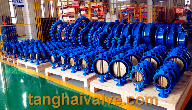
TH Valve is a professional manufacturer of butterfly valvegate valvecheck valveglobe valveknife gate valve, ball valve with API, JIS, DIN standard, used in Oil, Gas, Marine industry, Water supply and drainage, fire fighting, shipbuilding, water treatment and other systems, with Nominal Diameter of DN50 to DN1200, NBR/EPDM/VITON, Certificates & Approvals: DNV-GL, Lloyds, DNV, BV, API, ABS, CCS. Standards: EN 593, API609, API6D

Related news/knowledge:
What is the material of the main parts of the butterfly valve?-(1);
Valve body and material classification;
Comparison of bellows globe valve and ordinary globe valve;
What is the material of the butterfly valve stem?
Valve material and valve standards-(6)-gasket material

Valve seal (ring) material usage range comparison table

The selection of valve sealing material is determined according to the operating conditions of the valve, such as: pipeline medium, temperature range (high and low temperature), pressure and internal structure of the valve. For

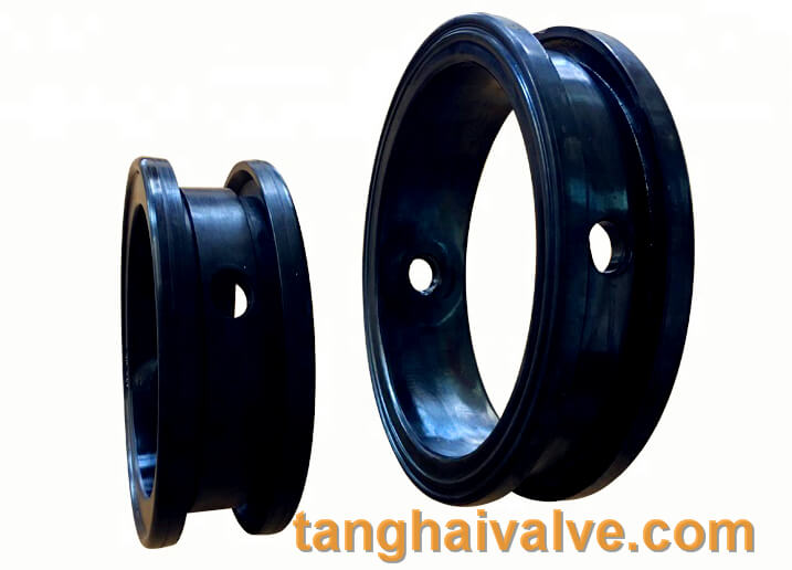
soft sealing marine valve, rubber sealing, valve seat parts

soft sealing marine valve, rubber sealing, valve seat parts

different occasions, the selected seals are also different. Valve seals can generally be divided into two categories: soft seals and hard seals. Users should have a detailed understanding of their codes, operating temperature, pressure, medium and other parameters.

Comparison table of valve sealing material usage range:
Valve sealing material and valve sealing material use range:
Rubber (X) Nominal pressure PN ≤ 1 MPa, operating temperature t ≤ 150℃, applicable valves: globe valves, diaphragm valves, butterfly valves, check valves, etc.
Nylon (N) Nominal pressure PN ≤ 32 MPa, operating temperature t ≤ 90°C, applicable valves: globe valves, ball valves, etc.
PTFE (F) Nominal pressure PN ≤ 6.4 MPa, operating temperature t ≤ 180°C, applicable valves: globe valves, ball valves, gate valves, diaphragm valves, butterfly valves, check valves, etc.
Bus alloy (B) Nominal pressure PN ≤ 2.5 MPa, operating temperature t ≤ 150°C, applicable valves: stop valves for ammonia, etc.
Ceramic (G) Nominal pressure PN ≤ 1.6 MPa, operating temperature t ≤ 150°C, applicable valves: ball valves, plug valves, etc.
Enamel (C) Nominal pressure PN ≤ 1.0 MPa, operating temperature t ≤ 80°C, applicable valves: globe valve, diaphragm valve, check valve, discharge valve, etc.
Copper alloy (T) Nominal pressure PN ≤ 1.6 MPa, operating temperature t ≤ 200℃, applicable valves: gate valve, globe valve, check valve, plug valve, etc.
Stainless steel (H) Nominal pressure PN ≤ 32 MPa, operating temperature t ≤ 450°C, applicable valves: globe valves, ball valves (medium and high pressure valves), etc.
Nitrided steel (D) Nominal pressure PN ≤ 10 MPa, operating temperature t ≤ 540℃, applicable valves: power station gate valves, only for general use
Cemented carbide (Y) Nominal pressure (PN) and operating temperature (t) are determined according to the material of the valve body. Applicable valves: high pressure, ultra high pressure valves, high temperature and low temperature valves

TH Valve is a professional manufacturer of butterfly valvegate valvecheck valveglobe valveknife gate valve, ball valve with API, JIS, DIN standard, used in Oil, Gas, Marine industry, Water supply and drainage, fire fighting, shipbuilding, water treatment and other systems, with Nominal Diameter of DN50 to DN1200, NBR/EPDM/VITON, Certificates & Approvals: DNV-GL, Lloyds, DNV, BV, API, ABS, CCS. Standards: EN 593, API609, API6D

Related news/knowledge:
Valve seal (ring) material usage range comparison table;
Comparison of bellows globe valve and ordinary globe valve;
Applicable occasions and operation method of ball valve;
How to choose a valve in the chemical industry

What is the positive transmission of gears

When the total displacement coefficient of a pair of gears is greater than 0, it is a positive transmission.
Positive transmission refers to the positive displacement design of the gear. If two gears meshing with each other are in positive displacement, their center distance is greater than (the pair of gears) standard center distance. Conversely, if both gears use negative displacement, the center distance is smaller than the standard center distance. To judge whether the position is shifted, it is mainly to compare the measured gear parameters (including center distance) with the standard parameters of the gear to draw a conclusion.
Gear transmission is the most widely used transmission form in mechanical transmission. It has relatively

accurate transmission, high efficiency, compact structure, reliable work and long life. At present, the achievable indexes of gear technology: peripheral speed v=300m/s, rotation speed n=105r/min, transmitted power P=105KW, modulus m=0.004~100mm, diameter d=1mm~152.3mm
Features
1, the instantaneous transmission ratio is constant. The instantaneous transmission ratio of non-circular gear transmission can be designed according to the required change law.
2, the transmission ratio range is large, which can be used to decelerate or increase speed.
3, the range of speed (pitch circle speed) and transmission power is wide, and it can be used for high-speed (v>40m/s), medium-speed and low-speed (v<25m/s) transmission; power is from less than 1W to 105KW.
4, high transmission efficiency. A pair of high-precision involute cylindrical gears has an efficiency of over 99%.
5, compact structure, suitable for short-distance transmission.
6, the manufacturing cost is higher. Certain gears with special tooth shapes or high precision require special or high-precision machine tools, cutting tools and measuring instruments, so the manufacturing process is complicated and the cost is high.
7, low-precision gears, noise, vibration and shock during transmission, pollute the environment.
8, no overload protection
According to the relative position of the two shafts and the direction of the gear teeth, it can be divided into the following types:
<1>Straight tooth cylindrical gear drive;
<2> Helical cylindrical gear drive
<3> herringbone gear transmission;
<4> bevel gear transmission;

bevel gear

bevel gear

<5> cross-axis helical gear transmission.
According to the working conditions of the gear, it can be divided into:
<1>; Open gear transmission type gear transmission, the gears are exposed, and good lubrication cannot be guaranteed.
<2>; half-open gear transmission, the gear is immersed in the oil pool, with a protective cover, but not closed.
<3>; closed gear transmission, gears, shafts and bearings are all installed in a closed box, with good lubrication conditions, difficult for dust and sand to enter, accurate installation,
Gear transmission has good working conditions and is the most widely used gear transmission.
Gear transmission can be classified according to the relative position of its axis.
Gear drive can be divided into cylindrical gear drive, bevel gear drive, non-circular gear drive, rack drive and worm drive according to the shape of the gear.
According to the tooth profile curve, it can be divided into involute gear transmission, cycloid gear transmission and arc gear transmission. A transmission composed of more than two gears is called a gear train. The gear transmission can be divided into ordinary gear transmission and planetary gear transmission according to whether there are gears with axis movement in the gear train. The gears with axis movement in the gear train are called planetary gears. Gear transmission can be divided into closed type according to its working conditions
Gear transmission calculation
Open and semi-open transmission. Sealing the transmission in a rigid case and ensuring good lubrication is called closed transmission, which is more commonly used, especially for higher-speed gear transmissions, which must be closed transmission. Open transmission is exposed and cannot guarantee good lubrication. It is only used for low speed or unimportant transmission. Half-open transmission is somewhere in between.
The law of meshing:  The smoothness of gear transmission requires the instantaneous transmission ratio in the process of gear tooth meshing i=angular speed of driving wheel/angular speed of driven wheel=ω1/ω2=constant, this requirement is guaranteed by tooth profile. Figure 2 shows that the two meshing tooth profiles E1 and E2 are in contact at any point K, and the common normal line N1N2 of the two tooth profiles is made through the point K, which intersects the connecting center line O1O2 at point C. The condition for maintaining contact during the meshing process of the two tooth profiles is that the velocity of the K point on the tooth profile E1, vK1, and the K point velocity on the tooth profile E2, vK2, are equal in the direction of the common normal line N1N2, that is, vKn1=vKn2=vKn. Make perpendicular lines from O1 and O2 to the N1N2 line and intersect at points N1 and N2. The above formula shows that the two-wheel tooth profile must meet the following conditions: “No matter where the two-wheel tooth profile is in contact at any position, the common normal line passing through the contact point must pass the fixed point C ─ ─ node on the connecting center line.” This is a circular gear. The basic law of tooth profile meshing. There are many curves that can meet this law. In fact, the requirements of manufacturing, installation and load-bearing capacity should be considered. Generally, only involute, cycloid and arc are used as the working tooth profile of the gear. Part of the tooth profile is involute.
For involute gears, the base radius rb1 and rb2 of wheel 1 and wheel 2 are respectively. The N1N2 line is the internal common tangent of the two base circles, that is, the common normal of any contact point of the two tooth profiles coincides with it. Because the two base circles have only one internal common tangent in one direction, the common normal of any contact point passes through the fixed point C, which shows that using an involute as the tooth profile conforms to the basic law of tooth profile meshing.
The two circles drawn through node C with O1 and O2 as the centers are called pitch circles. The pitch radius of wheel 1 and the pitch radius of wheel 2 Involute gears have the following characteristics: ①N1N2 is the trajectory of the contact points of the two tooth profiles, called the meshing line, which is a straight line. ②The common tangent line tt of the two pitch circles of gear transmission through node C is called the meshing angle α’between it and the meshing line N1N2, which is a constant. ③The pressure between the tooth surfaces is always along the direction of the common normal line N1N2 of the contact point, so the pressure direction between the tooth surfaces does not change when the involute gear transmits power. ④The transmission ratio is inversely proportional to the radius of the base circle of the two wheels. After the gear is made, the base circle is determined. Therefore, even if the center distance is slightly deviated from the design during operation, the transmission ratio will not be affected. This feature is called the separability of the transmission. It affects the processing, assembly and Maintenance is very beneficial. ⑤The two tooth profiles only have no sliding between the tooth surfaces when the node C is in contact, and there is sliding between the tooth surfaces when they are in contact at other points, and the farther away from the node, the greater the sliding. ⑥Since the involute gear can mesh with a rack with a linear tooth profile, it can be processed by a tool with a linear tooth profile. The tool is easy to manufacture and the machining accuracy can be high.
Coincidence degree: Coincidence degree is an important parameter that affects the continuous transmission of gears. As shown in Figure 2, gear tooth meshing starts from the contact between the tooth root of the driving wheel and the tooth tip of the driven wheel, that is, the intersection A of the tooth tip circle of the driven wheel and the meshing line is the starting point of meshing. As the wheel 1 rotates, the wheel 2 is pushed to rotate, and the contact point moves along the meshing line. When the contact point moves to the intersection E of the addendum circle of the wheel 1 and the meshing line (the dotted line in the figure), the tooth profile When the meshing ends, the two tooth profiles begin to separate. Point E is the meshing end point, which is the actual meshing line length. If the front pair of teeth are still in contact at point D before point E, and the latter pair of teeth are in contact at point A, then the transmission is continuous; if the front pair of teeth has left at point E, and the latter pair has not yet entered meshing , Then the transmission is interrupted. Considering the influence of gear manufacturing, installation errors and deformation, ε≥1.1~1.4 is often required in practice. The greater the coincidence degree, the more stable the transmission. The above refers to the coincidence degree of the end face of the cylindrical gear, and there is a longitudinal coincidence degree for the helical cylindrical gear.
The condition for a pair of gears to be able to mesh correctly is that they must have equal modulus and equal pressure angle.

TH Valve is a professional manufacturer of butterfly valvegate valvecheck valveglobe valveknife gate valve, ball valve with API, JIS, DIN standard, used in Oil, Gas, Marine industry, Water supply and drainage, fire fighting, shipbuilding, water treatment and other systems, with Nominal Diameter of DN50 to DN1200, NBR/EPDM/VITON, Certificates & Approvals: DNV-GL, Lloyds, DNV, BV, API, ABS, CCS. Standards: EN 593, API609, API6D

Related news /knowledge:
what is Spur gear?
Types of mechanical transmission;
Common failures of butterfly valves and the characteristics of installation
Stainless steel valve material parameters and specific applications

Accuracy requirements of Equipment installation

1. For static equipment
The vertical deviation of vertical equipment should not be greater than L/1000 and not greater than 10mm. Unless the drawings have special requirements.

lug type butterfly valve, ductile iron, center lined,

lug type butterfly valve, ductile iron, center lined,

The horizontal deviation of horizontal equipment should not be greater than L/1000 in the axial direction and 2D/1000 in the radial direction.

2. For moving equipment
When the pump is aligned, the selection of the installation datum and the allowable deviation of the level must meet the requirements of the “special specification” or the pump technical file. Generally, the allowable deviation of horizontal horizontality is 0.10mm/m, and the allowable deviation of vertical horizontality of the installation datum part is 0.05mm/m. The leveling and alignment values ​​must not be adjusted by loosening the anchor bolts.
1. The pump that is disassembled and installed is based on the processing surface of the pump body, and the allowable deviation of the horizontality of the pump in the vertical and horizontal directions is 0.05mm/m.
2. The integrally installed pump should be leveled based on the inlet and outlet flange surface or other horizontal processing datum plane. The allowable deviation of horizontality is 0.05mm/m in the longitudinal direction and 0.10mm/m in the transverse direction.
3. When the driving shaft and the driven shaft are connected by a coupling, the centering deviation of the two shafts and the gap between the end faces of the two shafts should be:
Centering deviation: the radial displacement is not more than 0.03mm.
The axial tilt should not be greater than 0.05/1000.
The end face gap is 1.00~3.5mm.

What is assembly error and how to control it?

Assembly error refers to the difference between the installation position of the parts and the ideal position required by the assembly specifications and design regulations and processes.

Causes of assembly errors:

Double flange butterfly valve (1)

Double flange butterfly valve (1)

①Part error: the additional error caused by the manufacturing error of the part and the deformation and wear after operation and use.
② Errors in tools and measuring tools: tools and quantities have manufacturing errors, and system errors will occur if they are used for measurement and positioning.
③Operation error: due to hand feeling (such as tightness, flatness, sharpness, smoothness, beating, shaking, vibration, spacing, pulling force, hand tapping, hand-hand gap, hand feeling loose, etc.), visual inspection (size, level, straight , Vertical, parallel, aligned, tangent, etc.), ear hearing (various abnormal noises), nose smell (leakage, etc.), the error generated by the human sensory identification.
④Environmental errors: errors caused by temperature, relative humidity, light direction, air flow direction, movement of the foundation, etc.
⑤ Consciousness error: error caused by lack of concentration or lack of responsibility.
How to control assembly error:
1. Choose a reasonable assembly benchmark
In order to make the assembly position of the part accurate, select a certain part (point, line, surface) of the already positioned part as the positioning basis for the part to be installed. This part is called the assembly datum. The correct choice of assembly benchmark is an important factor in improving assembly accuracy and reducing assembly errors, and must be taken seriously. The following factors should generally be considered for the correct selection of the assembly datum.
(1) Try to choose parts with higher machining accuracy, that is, parts with small dimensional tolerance, high shape accuracy, small position deviation, and low roughness as the reference. For example, the diameter tolerance and radial runout of the groove part during the manufacturing of the roller are lower than those of the smooth surface. Therefore, when checking the roller bending and correcting the roller gauge, the groove part is the reference.
(2) The reference position should be as close as possible to the assembly adjustment point. For example, when the car surface is flat, the height of the car surface should be adjusted by the frame lifting screw, so the flat ruler should be placed as close to the frame as possible. For example, if the flat-foot iron rest is placed far away from the frame, and the reference point is far away from the frame, when the height of the adjacent frame is adjusted, the iron rest will be driven to rise and fall to make the reference drift. As shown in Figure 1, suppose the center distance ab of the two frames is 1008mm, point a is the point where the top surface of the car has been leveled, and point b is the point where the top surface of the car is to be leveled. The flat ruler should be placed at point a. If it is not placed at point a, it should be placed at point d, 100mm (ad) away from point a. When correcting the length of the car to be horizontal, the car surface at the adjustment point is from point b Adjusted to point c, increased by 0.10mm (bc), this flat ruler bar was also driven to rise from point d to point e, rising by 0.01mm (de), that is, the benchmark is raised by 0.01mm.
This shows that the farther the flat-foot rail is from the frame, the greater the change in the height of the reference plane, which affects the assembly accuracy.
(3) Try to reuse the same datum as much as possible to eliminate the deviation of the part surface shape. For example, because the top surface has a certain degree of lengthwise bending and widthwise distortion, it is necessary to look at the length of the car surface to the level of the flat ruler, the level to look at the width of the car surface and the level of the front roller to support the height line. Line round rollers are placed in the same position to avoid additional errors caused by uneven top surface of the car.
(4) When selecting the benchmark, the convenience of flat mounting operation should also be considered. For example, there are generally two methods for positioning the helical gear of the spindle shaft: one is to insert the spindle, and use the spindle as the reference, and use the card board to locate; the other is to not insert the spindle, and the lower dragon-jin oil cup is the reference. Although the tolerance of the spindle diameter is smaller than the tolerance of the oil cup hole, it is more difficult to locate after inserting the spindle. Taking the oil cup hole as the reference, it can meet the left and right positioning requirements of the spindle gear, and the spindle can not be inserted, which makes the operation convenient.
(5) Try to be consistent with the reference parts of the machine manufacturer’s parts processing and pre-assembly.
2. Avoid multiple transmissions of assembly standards (reduce cumulative errors)
There are two ways to divide a 1m long straight line into ten equal parts: one is to use a 150mm steel ruler, and the steel ruler is moved every 1oomm for ten times; the other is to use 1m steel The ruler does not move, but takes ten points in sequence according to the corresponding scale line. It is obvious that the error of the second method is relatively small. Because of the former method, due to multiple movements of the measurement reference, two or more assembly errors (tools, operating errors) are superimposed together, and cumulative errors are generated. By the same token, when measuring the gap with a feeler gauge of specified degree, a single-page feeler gauge should be used as much as possible to measure more accurately, and avoid using two or more thin feeler gauges to measure.
3, master the law of change of error (eliminate system error)
If the variation law of the error is found and the value is ascertained, it is like trying to eliminate the error value during assembly. This kind of regular error is called systematic error. For example, when the inner diameter measuring claw of a vernier caliper wears out 0.02mm, making the reading of each measurement imaginaryly larger by 0.02mm, you can automatically subtract 0.02mm from the reading to get the actual reading you need. Another example is when the level of the bubble is inaccurate, after the positioning and U-turn inspection, it is found that the bubble is inaccurate. After positioning to a certain end, it is horizontal. Therefore, when looking at the level, you should deliberately make the main bubble to a certain end. , So that the parts reach a level state.
4. Reasonable allocation or adjustment error value (reduce assembly error)
1). Mutual loan
When large castings such as the drawing locomotive face, bottom plate, roving frame head and tail wall panels, frame, and face are twisted and deformed, due to the inconvenience of orthopedics, only the verticality or levelness of multiple points can be checked to make the readings positive and negative after flat mounting The maximum value of the direction is equal, or the difference after subtracting the maximum value of the positive and negative directions is not greater than the allowable error. This method is called the mutual loan method.
2). Adjustment method
When the cumulative error in assembly exceeds the allowable error, the size, shape or shape of one of the links can be changed, or an unimportant size can be discarded without control, so that the total size is within the allowable range. This changeable link is called the “adjustment ring”. For example, when adjusting the draw frame roller seat to open the gear, first determine the left and right positions of the upper wall panel from the outer line of the front of the car, and then set the first roller seat position based on the upper wall panel of the front of the car. Set the position of the second, third, and fourth roller seat in turn, and the size between the fourth roller seat and the upper wall panel of the car can only be abandoned, and it is impossible to correct it. In actual work, the size, shape or position of the adjustment ring Changes are often achieved by filing, padding, welding, or adjusting with adjustable parts, such as adjusting screws, adjusting washers, and foot pads. Using these parts to adjust can improve assembly accuracy and save manual work. File repair and other work.
3). Select right assembly method
In order to reduce assembly errors and improve the accuracy of parts assembly, parts with certain errors can also be matched or grouped through selection, so that the upper and lower errors between the parts can be matched to appropriately improve the accuracy, which is called selective assembly. For example, group the rubber roller core and the iron shell to make the gap consistent; divide the diameter of the rubber roller into several gears to make the diameter of the rubber roller of the same machine or the same zone be the same.

What is machining accuracy, machining error, tolerance?

1. Machining accuracy: the degree to which the actual geometric parameters (size, shape and position) of the part after processing are in line with the ideal geometric parameters. The higher the degree of conformity, the higher the processing accuracy.
2. Machining error: the degree of deviation of the actual geometric parameters of the part from the ideal geometric

U-type-flange-butterfly-valve-2

U-type-flange-butterfly-valve-2

parameters after processing is called the machining error. The magnitude of machining error indicates the level of machining accuracy, and machining error is a measure of machining accuracy.
3. Tolerance refers to the allowable error of the part processing clock.
What is the difference between them? “processing accuracy” and “processing error” are two different concepts for evaluating the accuracy of geometric parameters of parts. In the actual production, the method of controlling the processing error or the modern active adaptation processing method is used to ensure the processing accuracy.
Machining accuracy and machining error are described from different angles, but the size of the machining error is measured by the deviation of the actual measurement of the part, and the level of machining accuracy is measured by the tolerance level or tolerance value, and by the machining error To control the size. Generally speaking, the machining accuracy can only be guaranteed when the machining error is less than the tolerance.

What is the transmission ratio

In a mechanical transmission system, the ratio of the angular velocity or rotational speed of the driving wheel at the beginning and the driven wheel at the end.
Transmission ratio (i) = ratio of driving wheel speed (n1) to driven wheel speed (n2) = inverse ratio of gear index circle diameter = ratio of driven gear teeth (Z2) to driving gear teeth (Z1).
That is: i=n1/n2=D2/D1 i=n1/n2=z2/z1
For multi-stage gear transmission
1: The transmission ratio between every two shafts is calculated according to the above formula
2: The total transmission ratio from the first axis to the nth axis is calculated according to the following formula: Total transmission ratio ι=(Z2/Z1)×(Z4/Z3)×(Z6/Z5)……=(n1/n2)× (N3/n4)×(n5/n6)……

For multi-stage gear transmission

For multi-stage gear transmission

Extended information

The ratio of the angular velocities of the two rotating components in the mechanism is also called the speed ratio. The transmission ratio of component a and component b is Ⅰ=ωa/ωb=na/nb, where ωa and ωb are the angular velocities (radians/sec) of components a and b, respectively; na and nb are the rotational speeds of components a and b respectively ( Rpm) (Note: a and b after ω and n are subscripts).
When the angular velocity in the formula is an instantaneous value, the obtained transmission ratio is the instantaneous transmission ratio. When the angular velocity in the formula is an average value, the obtained transmission ratio is the average transmission ratio. For most gear transmissions and friction wheel transmissions with the correct tooth profile, the instantaneous transmission ratio is unchanged; for chain transmission and non-circular gear transmission, the instantaneous transmission ratio is variable.
For meshing transmission, the transmission ratio can be expressed by the number of teeth Za and Zb of wheel a and wheel b, i=Zb/Za; for friction transmission, the transmission ratio can be expressed by the radius Ra and Rb of wheel a and wheel b, i=Rb/Ra, At this time, the transmission ratio generally means the average transmission ratio.
In hydraulic transmission, the transmission ratio of the hydraulic transmission element generally refers to the ratio of the turbine speed S and the pump wheel speed B, that is, =S/B. Hydraulic transmission elements can also be combined with mechanical transmission elements (generally with various gear trains) to obtain various transmission ratios of different values ​​(see gear trains for gear train transmission ratios).