Maintenance of the Concentric type Butterfly Valve in Ships
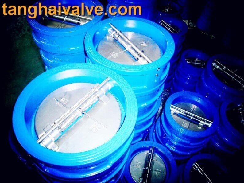
The maintenance of a concentric (centered) butterfly valve in ships is essential to ensure the valve’s optimal performance and longevity, especially in harsh marine environments. Concentric butterfly valves have the disc located in the center of the valve body, with a resilient seat that helps to seal the valve when closed. These valves are commonly used for fluid control in various ship systems, including seawater cooling, ballast systems, and bilge systems. Here’s a guide to maintaining a concentric butterfly valve on ships:
- Visual Inspection
External Inspection:Regularly check the valve for any visible signs of corrosion, wear, or damage, especially around the body, stem, and handle or actuator.
Marine environments are prone to corrosion due to saltwater, so special attention should be given to areas exposed to seawater.
Inspect for any salt deposits, marine growth, or other debris that may accumulate around the valve body and flanges.
Seal Inspection:Inspect the valve’s seat (usually made of rubber or elastomer) for wear or damage. The seal is crucial for the valve’s tight closure.
Check for cracks, deformities, or wear in the seal that could lead to leakage. The seal is one of the most critical parts, and its condition directly affects valve performance.
- Regular Cleaning
Valve Cleaning:Clean the exterior and interior of the valve regularly to remove any buildup of marine organisms, rust, silt, or debris that may impair its function.
Use approved marine cleaning agents that do not damage the valve’s materials. After cleaning, thoroughly rinse the valve with freshwater to remove any residual chemicals.
Seal and Disc Cleaning:Gently clean the valve’s disc and seat to remove any deposits. Marine organisms, like barnacles or algae, can settle on the disc, potentially impacting valve closure.
- Lubrication
Stem and Moving Parts:
Lubricate the stem and other moving parts of the valve as per the manufacturer’s recommendations. Marine-grade lubricants should be used to prevent corrosion and ensure smooth operation.
Avoid over-lubricating, as excess lubricant can attract dirt or debris.
Actuator Lubrication (for automated valves):
If the valve is equipped with an actuator (pneumatic, hydraulic, or electric), ensure that the actuator’s moving parts are adequately lubricated. Regularly check actuator connections to ensure they are secure and functioning smoothly.
- Operational Testing
Open and Close Testing:Periodically operate the valve by fully opening and closing it to ensure the disc moves freely. A valve that isn’t operated regularly may become stiff or difficult to operate due to corrosion, buildup, or seal hardening.
Ensure that there are no sticking points, and check the valve handle or actuator for any issues.
Leakage Testing:Perform a hydrostatic or pneumatic test at operating pressure to detect any leaks. If leakage is found, inspect the seat, seal, and disc for damage.
For valves under critical operation (e.g., seawater intake or discharge), this test should be part of routine inspections.
- Seal Replacement
Seal and Seat Maintenance:
The resilient seat is a key component that provides a bubble-tight seal in a concentric butterfly valve. Over time, the seat can wear out or become damaged due to constant use or exposure to chemicals, requiring replacement.
Replace the valve seat if you notice signs of cracking, deformation, or excessive wear that could compromise its sealing ability.
Stem Seals:
Inspect the stem seals (o-rings or gaskets) for wear. If these seals fail, it could lead to leakage around the stem area.
- Corrosion Protection
Protective Coating:
Apply protective coatings, like marine-grade anti-corrosive paints, to the external parts of the valve that are exposed to saltwater or humid environments.
If the valve is made from a material prone to rust (such as certain grades of cast iron), extra attention should be given to keeping the body protected from corrosion.
Material Compatibility:
Ensure that the valve material (body and disc) is suitable for the specific fluid or gas being handled. Corrosion-resistant materials like stainless steel or bronze should be used for seawater applications.
- Actuator and Control System Maintenance
Actuator Inspection:
For automatic valves, inspect the actuator system regularly. Check for signs of wear, corrosion, or malfunction in the actuator.
Ensure the actuator’s control signals are accurate, and the valve opens and closes fully when triggered.
Control System Calibration:
If the valve is part of an automated control system, periodically calibrate the system to ensure it operates at the correct parameters (e.g., pressure or flow settings).
- Bolts and Flange Check
Tightness of Flange Bolts:Periodically check the tightness of the bolts securing the valve to the pipe flanges. Marine vibrations can loosen these bolts over time.
Use the manufacturer-recommended torque settings when tightening bolts to avoid over-tightening or damaging the valve body.
- Gasket Inspection
Flange Gasket:Check the condition of flange gaskets between the valve and pipe flanges. If leaks are detected, the gasket may need to be replaced.
Gaskets exposed to high pressure, temperature, or aggressive fluids might degrade faster and require more frequent replacement.
Summary of Key Maintenance Practices:
Regular inspection: Visual and operational checks for corrosion, leaks, and damage.
Cleaning: Routine cleaning of valve components to remove marine growth and deposits.
Lubrication: Ensure moving parts are lubricated using marine-grade products.
Seal and gasket maintenance: Inspect and replace the valve seat, stem seals, and flange gaskets as needed.
Operational tests: Open and close the valve to ensure smooth operation.
Corrosion protection: Apply anti-corrosion coatings and ensure material compatibility with seawater.
Maintenance Schedule:
Weekly: Visual inspections, operational testing, and cleaning of external surfaces.
Monthly: Internal cleaning, actuator system checks, and lubrication.
Annually: Comprehensive inspections, including seal, gasket, and bolt checks; perform leakage tests and replace worn-out components.
Maintaining concentric butterfly valves on ships is crucial for ensuring the reliability of fluid systems, preventing leaks, and extending the valve’s service life.
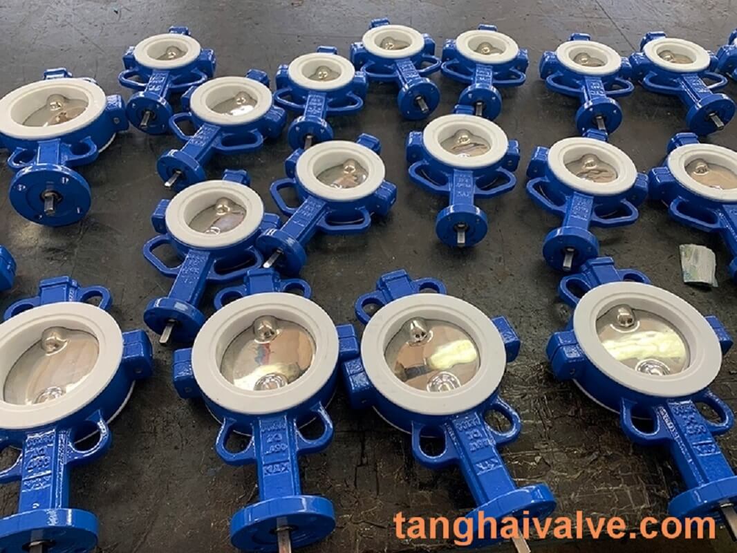
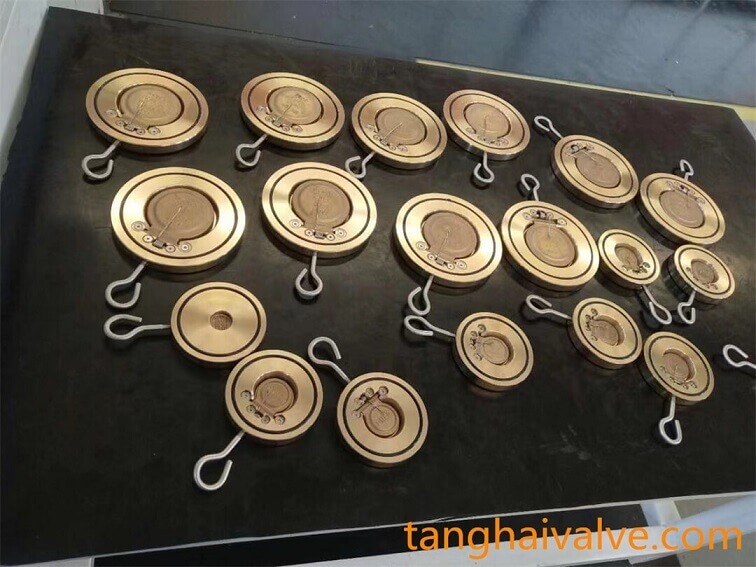
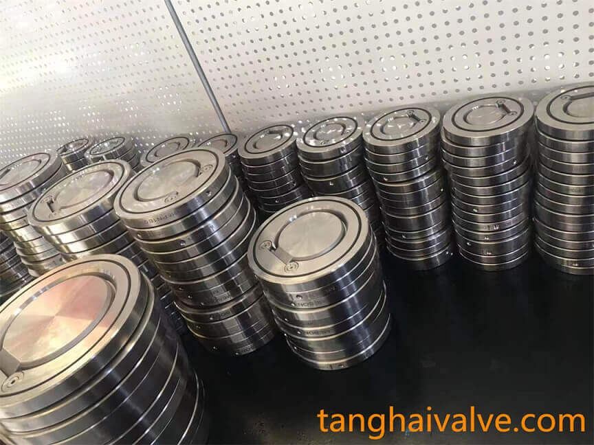
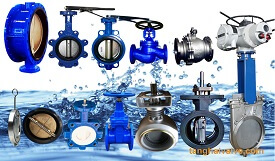
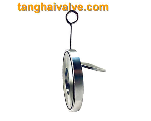
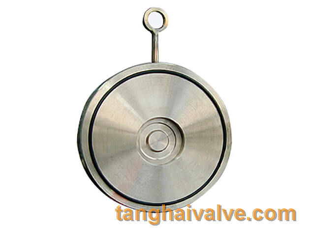
Tianjin Tanghai Valve Co., Ltd. is a professional marine valve manufacturer, including butterfly valve, check valve, gate /Knife gate valve. We have certificates: CE, ISO, BV, DNV foundry and products approval. Now we have our own independent R & D, manufacturing, assembly and warehousing workshops; we have professional pre-sale and after-sale technical support and perfect services. Below is our wafer butterfly valve of marine valves,if you need to check more information, please click here: https://www.tanghaivalve.com/wafer-type-butterfly-valve-th-btv-aw/
Please contact us if you need more support, please contact us freely: info@tanghaivalve.com.We are committed to “Build a top valve enterprise; Be a reliable partner!”Friends from all over the world are welcome to visit us for evaluation, guidance, and orders!