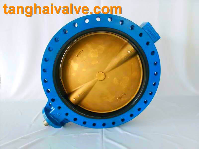
A concentric butterfly valve with a carbon steel body is a common type of valve used in industrial applications for regulating or isolating the flow of fluids. The concentric design means that the valve disc and stem are aligned on the same axis, making it suitable for low-to-moderate pressure applications. Below are the key features of this type of valve:
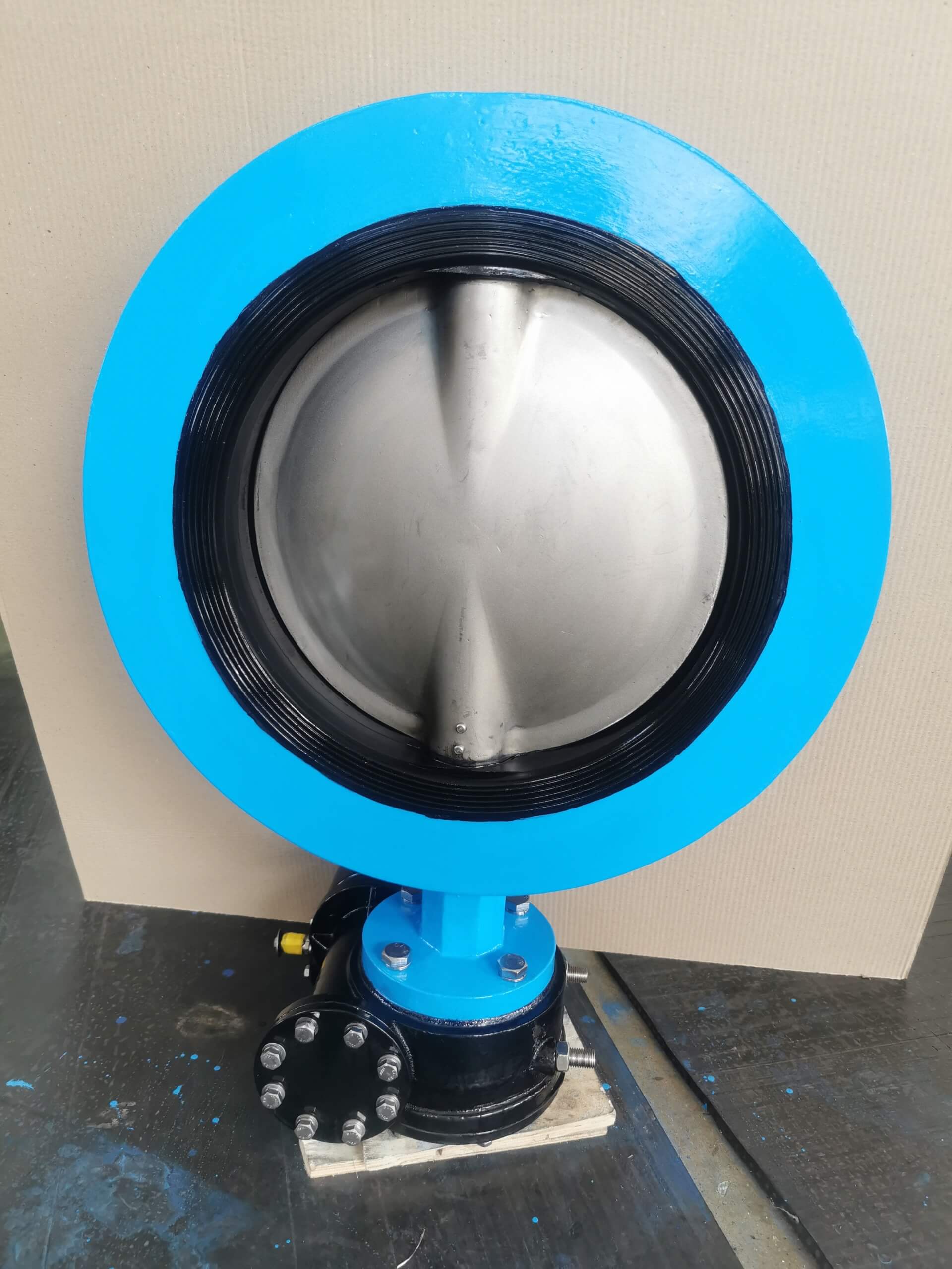
- Concentric Design (Centerlined)
Shaft and Disc Alignment: The shaft (or stem) is centrally located in the valve body, and the disc rotates on the same axis as the shaft. This allows for even pressure distribution on the valve seat.
No Offsets: Unlike offset butterfly valves, concentric valves have no displacement of the shaft relative to the seat and disc, making them simpler and easier to maintain.
- Carbon Steel Body
Material Strength: Carbon steel is strong and durable, suitable for applications that involve moderate pressure and temperature.
Corrosion Resistance: Carbon steel provides moderate corrosion resistance but may require external coatings (such as epoxy) or internal linings to protect against aggressive chemicals or moisture.
Temperature Tolerance: Carbon steel can withstand relatively high temperatures (up to approximately 425°C or 800°F), making it appropriate for steam, oil, or gas applications.
Cost-Effective: Carbon steel is less expensive compared to stainless steel, making it a cost-effective solution for many industrial applications.
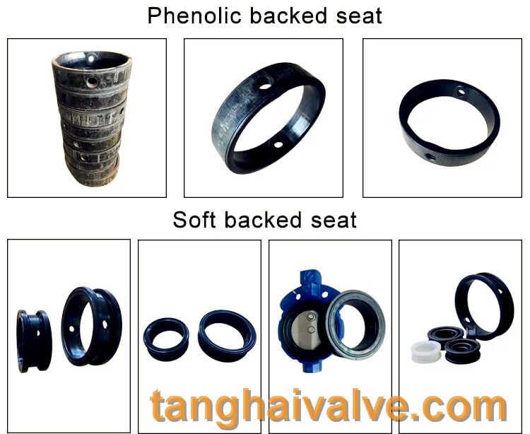
- Soft Seat
Elastomeric Seat: Concentric butterfly valves typically use soft seats made from elastomeric materials like EPDM, Nitrile (Buna-N), or PTFE. These materials provide a bubble-tight seal, especially in low-pressure applications.
Replaceable Seat: The seat is often replaceable, which allows for easy maintenance and longer valve life.
Leakage Protection: Soft seats offer good sealing performance and can achieve zero leakage (Class VI shutoff).
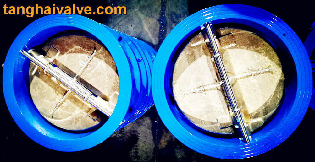
- Disc Design
Material: The disc is typically made of stainless steel, ductile iron, or other alloys to provide enhanced corrosion resistance in different environments.
Low Flow Resistance: When the valve is fully open, the disc is parallel to the flow of the fluid, resulting in minimal flow resistance and a low-pressure drop.
Tight Shutoff: The disc is designed to provide tight shutoff, making the valve ideal for applications where leakage prevention is critical.
- Bi-Directional Flow
The concentric butterfly valve is capable of controlling the flow of fluids in both directions, enhancing its versatility in piping systems.
- Low Torque Requirement
The concentric design requires low torque for operation. This makes the valve easier to operate manually and reduces the power needed for actuation when automated.
- Compact and Lightweight
Space-Saving: Butterfly valves are compact and lightweight compared to other valve types like gate or globe valves. This makes installation easier and reduces the weight on piping systems, especially in larger diameter applications.
- Wafer or Lug Type Connection
Wafer Type: Designed to fit between two flanges using long bolts that pass through both flanges and the valve body.
Lug Type: Features threaded inserts, allowing the valve to be installed between flanges and secured with bolts on each side. This enables removal of downstream piping without disturbing the upstream piping.
- Operation Options
Manual Operation: Operated using a handwheel or lever for simple, on/off control.
Automated Operation: The valve can be equipped with pneumatic, electric, or hydraulic actuators for remote or automated control.
- Applications
Suitable for low-to-moderate pressure and temperature applications in industries like:Water Treatment: Used in pipelines for water distribution and wastewater treatment.
HVAC Systems: Applied in heating, ventilation, and air conditioning systems for flow regulation.
Oil & Gas: Used in gas transmission pipelines, oil refineries, and other industrial applications involving non-corrosive fluids.
Chemical Processing: Ideal for handling non-corrosive chemicals, light acids, and alkaline solutions.
Power Generation: Common in cooling water and steam lines.
- Easy Maintenance
The simple design of the concentric butterfly valve with fewer moving parts allows for easy maintenance. The seat and disc are generally replaceable, reducing downtime and operational costs.
- Pressure and Temperature Range
Pressure Rating: Typically suitable for low to medium pressure applications (up to 300 PSI or higher depending on the design).
Temperature Range: Can handle a wide range of temperatures, especially when paired with appropriate seat materials. However, soft-seated valves are more suitable for moderate temperature ranges.
- Cost-Effective Solution
Concentric butterfly valves with carbon steel bodies offer an economical solution for applications where high durability, moderate pressure handling, and cost-efficiency are required, making them popular for general-purpose use in industries like water treatment, HVAC, and oil and gas.
Summary of Key Benefits:
Cost-Effective: Carbon steel is affordable, and concentric valves are simpler in design.
Durable: Withstands moderate temperature and pressure applications.
Compact: Saves space and reduces the overall weight of the piping system.
Easy to Maintain: Simple design with replaceable parts.
Versatile: Suitable for water, gas, steam, and light chemical handling.
These features make concentric butterfly valves with carbon steel bodies ideal for a variety of applications that require reliability, cost-efficiency, and easy maintenance.
Tianjin Tanghai Valve Co., Ltd. is a professional marine valve manufacturer, including butterfly valve, check valve, gate /Knife gate valve. We have certificates: CE, ISO, BV, DNV foundry and products approval. Now we have our own independent R & D, manufacturing, assembly and warehousing workshops; we have professional pre-sale and after-sale technical support and perfect services. Below is our wafer butterfly valve of marine valves,if you need to check more information, please click here: https://www.tanghaivalve.com/wafer-type-butterfly-valve-th-btv-aw/
Please contact us if you need more support, please contact us freely: info@tanghaivalve.com.We are committed to “Build a top valve enterprise; Be a reliable partner!”Friends from all over the world are welcome to visit us for evaluation, guidance, and orders!