Tag Archive for: valve

Posts

Code of valve sealing or lining material

The sealing surface of the valve mainly refers to the contact surface of the valve disc and the valve seat. The sealing

marine valve seat

marine valve seat

element plays the role of cutting off and connecting, adjusting and distributing, separating and mixing the medium on the valve passage, and improving the quality and service life of the valve sealing surface. Appropriate sealing surface materials and reasonable sealing structure must be selected. Valve sealing ring materials are mostly mixed materials, and seals of different components have different effects. When selecting valves, customers should choose corresponding seals according to the actual conditions of the medium, temperature and pressure.

code sealing material/lining material
T Copper alloy
X Rubber
N Nylon plastic
F Fluoroplastic
B Babbitt alloy
H Alloy steel
D Nitrided steel
Y Hard alloy
J Lining
Q Lead lining
C Enamel
P Boronized steel

Note:

1. The code of the valve seat sealing material directly processed by the valve body is coded by “W”.
2. When the sealing materials of the valve seat and the valve disc (valve plate) are different, it is indicated by the code of low hardness material (except for diaphragm valves).

Types and selection of electric valves

Types of electric valves:
Electric valves are valves driven by electric energy, mainly composed of electric actuators and various types of valves.

double eccentric butterfly valve (2)

double eccentric butterfly valve (2)

Because the electric valve is easy to use and can be operated when the power is turned on, it is the longest-used type of automatic control valve. There are many types of electric valves. Commonly used are electric control valves, electric ball valves, electric butterfly valves, electric gate valves, and electric globe valves. Different types of electric valves have different applications.

1. The electric control valve can choose different valve structures and spool types according to the working conditions of the medium. It is mainly suitable for high, medium and low pressure pipelines with various media to adjust pipeline parameters. With the increasing requirements in the field of modern industrial automation, electric control valves are becoming more and more widely used. Different materials can be used to use various liquid and gas media pipelines.

2. Electric ball valve and electric butterfly valve are the most widely used electric valve models, equipped with different actuators, which can not only realize the two-position cut-off of the pipeline, but also can be used for occasions where the linearity requirements are not too strict. Electric butterfly valves There are two connection methods: wafer type and flange type. Normal pressure and large diameter pipes are mostly used. Electric ball valves and electric butterfly valves are similar in use, but they use more pressure than electric butterfly valves.

3. Both the electric gate valve and the electric shut-off valve have a blocking function in the pipeline, but it should be noted that these two types of valves cannot be used for adjustment. It is suitable for all kinds of large diameter, high, medium and low pressure medium working conditions.

Electric valve selection:
Electric valves are usually valves that are driven by a motor. Because the motor needs to be decelerated to drive the valve to open and close, it is generally not recommended to use electric if it is required to close and open the valve quickly. Basically, you can choose electromagnetic quick-closing valve, pneumatic or hydraulic quick-closing valve. Close the valve. But if necessary, you must choose an electric type of quick-closing valve, then you should choose an electric butterfly valve or an electric ball valve, because this type of valve has a short switching stroke.

Lining material and its application scope of fluorine lined valve

Description of lining material of fluorine-lined valve
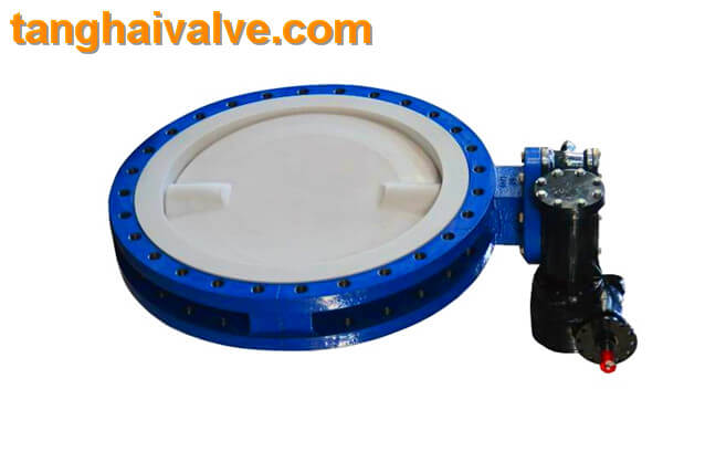
With the maturity of the fluorine lining process, the varieties of fluorine lining valves are becoming more and more

U type flange butterfly valve (3)

U type flange butterfly valve (3)

abundant, including fluorine diaphragm valves, fluorine butterfly valves, fluorine ball valves, fluorine check valves, fluorine globe valves, and fluorine filters. The biggest advantage of fluorine-lined valves is to control strong corrosive media, with a pressure rating of 0.6-1.6Mpa, which is suitable for working conditions with a temperature within 150°C. However, there are many types of lining materials for fluorine-lined valves, and different materials are suitable for different media and temperatures. Users should choose the correct type according to the actual working conditions.

Fluorine-lined valve lining material applicable table
Polyperfluoroethylene FEP (F46) Applicable medium: any organic solvent or reagent, dilute or concentrated inorganic acid, alkali, ketone, aromatic hydrocarbon, chlorinated hydrocarbon, etc.   Operating temperature: -85~150℃ Features: The mechanical, electrical properties and chemical stability are basically the same as F4, but the outstanding advantage is high dynamic toughness, excellent weather resistance and radiation resistance.
Polytrifluoroethylene PCTEF(F3) Applicable medium: various organic solvents, inorganic corrosive liquids (oxidizing acids)    Operating temperature: -195~120℃ Features: heat resistance, electrical properties and chemical stability second only to F4, mechanical strength, creep properties, hardness Better than F4
Polypropylene RPP Applicable medium: aqueous solutions of inorganic salts, dilute or concentrated solutions of inorganic acids and alkalis. Operating temperature: -14~80℃ Features: one of the lightest plastics, its tensile and compressive strength at yield, hardness is better than that of low-pressure polyethylene, outstanding rigidity, good heat resistance, easy to form, and cheap. After modification, it has dynamic impact, fluidity and bending elasticity.
Rigid PVC Applicable medium: water resistant, concentrated alkali, non-oxidizing acid, chain hydrocarbon, oil and ozone, etc.   Operating temperature: 0-55℃ Features: high mechanical strength, excellent chemical stability and dielectric properties, good oil resistance and aging resistance, easy welding and bonding, and low price.
Polytetrachloroethylene PTFE (F4) Use medium: strong acid, strong base, strong oxidant, etc.   Operating temperature: -200~180℃ Features: Excellent chemical stability, high heat resistance, cold resistance, low friction coefficient, it is an excellent self-lubricating material. But the mechanical properties are low, the fluidity is poor, and the thermal expansion is large.
Polyvinylidene chloride PVDF (F2) Use medium: resistant to most chemicals and solvents, operating temperature: -70~100°C Features: tensile strength and compressive strength are better than F4, bending resistance, weather resistance, and radiation resistance. Light resistance and aging, etc., the biggest feature is good toughness and easy forming.
Polyolefin PO Applicable medium: various concentrations of acid-base salts and certain organic solvents.   Operating temperature: -58~80℃ Features: It is the most ideal anti-corrosion material in the world at present, and it has been widely used in the lining of large-scale equipment and pipe fittings of rotational molding.

Related products:
wafer butterfly valve; lug butterfly valve; double flange butterfly valve;
Double eccentric butterfly valve

TH Valve is a professional manufacturer of butterfly valvegate valvecheck valveglobe valveknife gate valve, ball valve with API, JIS, DIN standard, used in Oil, Gas, Marine industry, Water supply and drainage, fire fighting, shipbuilding, water treatment and other systems, with Nominal Diameter of DN50 to DN1200, NBR/EPDM/VITON, Certificates & Approvals: DNV-GL, Lloyds, DNV, BV, API, ABS, CCS. Standards: EN 593, API609, API6D

Related news/knowledge:
Fluorine-lined valve instructions | Installation instructions;
Code of valve sealing or lining material;
Classification and selection of fluorine-lined valves

Classification and selection of fluorine-lined valves

Fluorine-lined valves, anti-corrosion valves, corrosion-resistant special valves

Introduction to fluorine-lined valves and corrosion-resistant valves:
Fluorine-lined valve, also known as fluorine-lined plastic corrosion-resistant valve, is a method of molding (or inlaying) polytetrafluoroethylene resin and placing it on the inner wall of the valve pressure part or the outer surface of the valve inner part. (The same method applies to all The lining of similar pressure vessels and pipeline accessories), using its unique performance in resisting strong corrosive media, is made into a special corrosion-resistant valve. Simply put, fluorine-lined valve is to use the lining process for all the places in the valve body that the medium can reach.

The lining material of fluorine-lined valves generally adopts FEP (F46) and PCTFE (F3) and other fluoroplastics,

double eccentric butterfly valve (6)

double eccentric butterfly valve (6)

which can be applied to various concentrations of sulfuric acid, hydrochloric acid, hydrofluoric acid, aqua regia and various organic acids, strong acids, strong oxidants and others Corrosive media and other pipelines, but fluorine-lined valves are relatively limited by temperature, and are only suitable for media between -50°C and 150°C.

Classification of fluorine-lined valves and corrosion-resistant valves:
Common fluorine-lined plastic valves are: fluorine-lined butterfly valves, fluorine-lined ball valves, fluorine-lined globe valves, fluorine-lined diaphragm valves, fluorine-lined gate valves, fluorine-lined plug valves, etc.
1. Fluorine lined ball valve
The ball valve with fluoroplastic lining layer has extremely high chemical stability and is suitable for any strong corrosive chemical medium. The structure is a full-pass floating ball valve structure. The element leakage closes in the entire pressure range, which is convenient for the pipeline system to pass Ball sweep line and pipeline maintenance.
2. Fluorine-lined butterfly valve
Used in occasions requiring reliable sealing and good adjustment characteristics. The valve body of the fluorine-lined butterfly valve adopts a split type, and the sealing of the current end of the valve shaft is controlled by adding fluorine rubber to the rotating base surface between the butterfly plate and the valve seat, so as to achieve compact structure, beautiful appearance, reasonable process and reliable performance. The fluorine-lined butterfly valve ensures that the valve shaft does not contact the fluid medium in the cavity. It is very convenient to replace the valve shaft. The fluorine-lined butterfly valve can be completed without removing the pipeline.
3. Fluorine lined gate valve
One of the most common open-close valves, which use wedge-shaped gates sealed on both sides to connect or cut off the medium in the pipeline. The wedge gate valve does not allow a small amount of opening to be used as a throttling device in the pipeline to avoid high-speed flow The medium erodes and accelerates the damage of the sealing surface.
4. Fluorine-lined plug valve
The structure is compact and reasonable, the internal cavity space of the valve is minimal, and the medium retention is reduced. In addition, the special molding process makes the sealing surface dense, and the combination of herringbone ring PTFE packing enables the valve to achieve zero leakage; this series is for various It is designed for automatic opening and closing control of the pipeline of strong corrosive medium.
5. Fluorine-lined globe valve
The valve can be unblocked or blocked by lifting the valve flap. The valve flap and the inner side of the valve body are all made of fluoroplastic lining. It has the advantages of light switch, small size, reliable sealing, simple structure, convenient maintenance and wide range of use.
6. Fluorine-lined check valve
The fluorine-lined check valve only allows the medium to flow in one direction and prevents the flow in the opposite direction. Usually this fluorine-lined check valve works automatically. Under the pressure of one direction, the valve flap opens and the liquid flows in the opposite direction. There are liquid pressure and the weight of the valve flap, and the closing valve flap acts on the valve weight to cut off the flow. Fluorine-lined check valve includes lift check valve, swing check valve, wafer check valve and so on. H41F46 fluorine-lined check valve is suitable for various concentrations of aqua regia, sulfuric acid, hydrochloric acid, hydrofluoric acid and various organic acids, strong acids, and strong oxidants at -50℃~150℃. FEP is also suitable for various concentrations of strong alkali Use on pipelines of organic solvents and other corrosive gases and liquid media.

The difference and selection of electric valve and pneumatic valve

With the progress and continuous reform of the times, my country’s valve products have also been innovated with the change of the times. At present, in the valve market where environmental protection and safety are increasingly
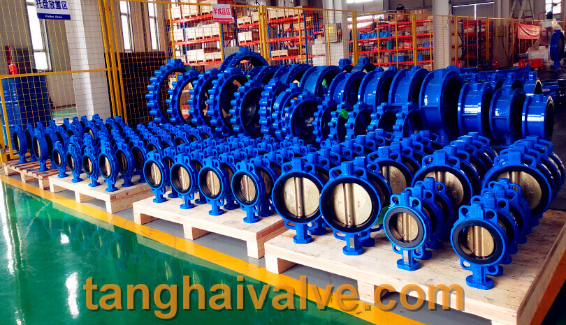
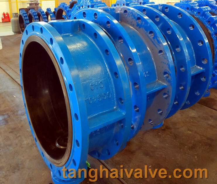
ductile iron, DI, butterfly valve, manufacturer, center line, TH valve

ductile iron, DI, butterfly valve, manufacturer, center line, TH valve

demanded, the use of automatic control devices such as electric valves and pneumatic valves is gradually becoming impossible Optional. The use of self-control valves is more energy-saving, safer and more reliable. Compared with the traditional manual valve, the movement speed is faster than the ordinary valve, which not only reduces the manpower, but also greatly improves the work efficiency.
Compared with the pneumatic valve, the electric valve has a simple structure and reliable operation, and its power source (power source or air source) is easy to solve for the remote operation point. The disadvantage is that the price is higher and the explosion-proof requirements are also higher. When selecting, comprehensive consideration should be given to factors such as the
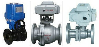
electric ball valve

electric ball valve

availability, price and control requirements of the power source. The selection of the valve generally first confirm the valve material, valve diameter, medium type, pipeline pressure, connection mode, control mode, medium temperature etc.

Electric valve selection: When electric valve is selected (the control mode of electric actuator is generally divided into on-off type and regulating type), in addition to the basic valve body diameter, pressure, material and other requirements, the following parameters should be provided:
1. Power supply parameters (including voltage, number of phases and frequency);
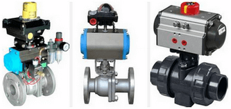
pneumatic ball valve

pneumatic ball valve

2. Running time and form of electric actuator;
3. Whether explosion-proof and explosion-proof grade are required;
4. Atmospheric protection level;
5. Overload protection requirements, such as over travel protection, over torque protection, etc.;
6. Local operation requirements, such as whether to bring a local operation handwheel;
7. Operation instruction requirements.
Pneumatic valve selection: When selecting pneumatic valves (the operating principle of pneumatic actuators can be divided into single-acting and double-acting), in addition to determining specific parameters such as valve body diameter, pressure, and material, the following parameters should also be provided:
1. Air source parameters (including air source pressure range, whether to bring your own gas storage tank, etc.)
2. Running time and form of pneumatic actuator
3. Whether explosion-proof and explosion-proof grade are required;
4. Atmospheric protection level;
5. Overload protection requirements, such as over travel protection, over torque protection, etc.;
6. Local operation requirements, such as whether to bring a local operation handwheel;
7. Operation instruction requirements.
As the level of industrial automation requirements has increased significantly, the demand for electric (pneumatic) valves is also increasing, and the control requirements for electric (pneumatic) valves have become more and more detailed and complex. For the correct selection of electric (pneumatic) valves, it not only involves the correct use of the product, but also may affect the safety of the entire pipeline system. Users should understand and understand the relevant selection knowledge.

TH Valve is a professional manufacturer of butterfly valvegate valvecheck valveglobe valveknife gate valve, ball valve with API, JIS, DIN standard, used in Oil, Gas, Marine industry, Water supply and drainage, fire fighting, shipbuilding, water treatment and other systems, with Nominal Diameter of DN50 to DN1200, NBR/EPDM/VITON, Certificates & Approvals: DNV-GL, Lloyds, DNV, BV, API, ABS, CCS. Standards: EN 593, API609, API6D

Related news/knowledge:
Applicable occasions and operation method of ball valve;
working principle of electric globe valve;
Notes on selection and installation of butterfly valve;
Description of electric valve connection
Description and classification of valve connection

Classification and description of valve connection methods: Nowadays, the application range of valves is wider and

double flange butterfly valve body

double flange butterfly valve body

wider, and corresponding valves should be used in different environments. The connection between the entire valve and the pipeline or equipment is different. Regardless of installation, use and maintenance, attention should be paid to the improper connection of the valve, which may cause the valve to run, leak, drip, and leak. Therefore, valve users should be treated in accordance with the situation of the user.
There are many types of valve connection. Common valve connection methods are: flange connection, butt connection, butt welding connection, thread connection, ferrule connection, clamp connection, self-sealing connection and other connection forms. This article will focus on the most common flange connection, butt welding connection and threaded connection in the installation process easy to explain the problems, I hope to help everyone.

Threaded valve: A simple connection method, often used for small valves. This connection is usually made by processing the valve inlet and outlet ends into tapered pipes or straight pipe threads, which can be connected to tapered pipe threaded joints or pipelines. Since this connection may have large leakage channels, sealants, sealing tape or fillers can be used to plug these channels. If the material of the valve body can be welded, but the expansion coefficient is very different, or the working temperature has a large range of variation, the threaded connection must be honey sealed. Threaded valves are mainly valves whose nominal diameter is below 50mm. If the diameter size is too large, the installation and sealing of the connection part will be very difficult. In order to facilitate the installation and removal of threaded valves, pipe joints can be used at appropriate positions in the pipeline system. Valves with a nominal diameter below 50mm can use pipe sockets as pipe joints, and the thread of the pipe socket connects the two connected parts together. …
Flanged valve: Flanged valve, the most used connection form among valves. Its installation and disassembly are relatively convenient. But it is heavier than the threaded valve, and the corresponding price is higher. Therefore, it is suitable for pipe connections of various diameters and pressures. However, when the temperature exceeds 350 degrees, the bolts, gaskets and flanges become loose, and the load of the bolts is significantly reduced, which may cause leakage to the flange connection with a large force.
Welded valve This connection is suitable for various pressures and temperatures, and is more reliable than flanged connections when used under heavy load conditions. However, it is difficult to disassemble and reinstall the valve connected by welding, so its use is limited to the occasions that usually can operate reliably for a long time, or where the use conditions are heavy and the temperature is high. Such as the pipelines of thermal power stations, nuclear power projects, and ethylene projects. Welded valves with a nominal diameter of less than 50mm usually have welding sockets to accept the pipeline at the end of the load. Since socket welding forms a gap between the socket and the pipe, it is possible that the gap will be corroded by some media. At the same time, the vibration of the pipe will fatigue the connection part, so the use of socket welding is limited. In the occasions where the nominal diameter is large, the use conditions are heavy, and the temperature is high, the valve body is often welded with grooves. At the same time, there are original requirements for the welding seam, and a skilled welder must be selected to complete this work.

TH Valve is a professional manufacturer of butterfly valvegate valvecheck valveglobe valveknife gate valve, ball valve with API, JIS, DIN standard, used in Oil, Gas, Marine industry, Water supply and drainage, fire fighting, shipbuilding, water treatment and other systems, with Nominal Diameter of DN50 to DN1200, NBR/EPDM/VITON, Certificates & Approvals: DNV-GL, Lloyds, DNV, BV, API, ABS, CCS. Standards: EN 593, API609, API6D

Related news/knowledge:
Resilient seated socket end gate valve;
Commonly used valve body material code description;
The difference between internally and externally threaded valves;
Classification of check valves

Raised face flange and concave and convex face flange

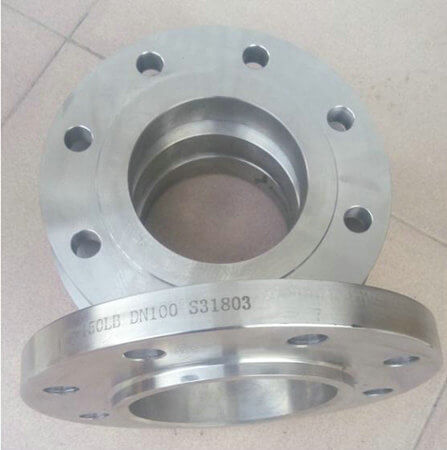
Flange is used for the connection between two devices. The abbreviation refers to the form of the sealing surface. There are holes on it. The two flanges are connected by bolts. It is generally used for The mutual connection between

flanges

flanges

the shaft and the shaft is also used for the connection between the pipe ends; it is a detachable connection of a set of combined sealing structures that are connected by flanges, gaskets and bolts. The thickness of flanges with different pressures is different, and their use forms are also different.

Commonly used butterfly valves include wafer butterfly valves and flange butterfly valves. Wafer type butterfly valve uses double-head bolts to connect the valve between two pipe flanges. Flange type butterfly valve has flanges on the valve, and the two ends of the valve are flanged to the pipe flanges with bolts.
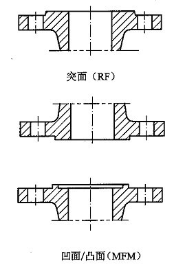
For the most common raised face flanges and concave and convex face flanges, in the flange connection, the raised face flange needs to be matched with the concave face flange, commonly known as one male and one female, and the raised face flange should be matched with the raised face flange. Generally speaking, raised face flanges should also be a kind of flat flanges, code-named RF, and the RF face can only be linked with the RF face. The code name of the raised face flange is M, and the M face flange needs to be connected with the FM face. One is female FM (Female Male), and the other is male M (Male). The pressure on the M/FM side is better than that on the RF side. Raised face flanges and raised face flanges are used in pairs, and the code name is RF. The comparison chart of the two is as follows:

RF, MFM flanges

RF, MFM flanges

The angle between the sealing surface of the raised face flange and the flange bolt connection surface is 45°, and the sealing surface of the concave and convex flange and the flange bolt connection surface are 90° angle, that is, the two sides are perpendicular .

Raised face flanges are more commonly used in the market, and generally there is no problem below 2.5MPa. Concave-convex flanges are more expensive and have better sealing effect, so the applicable pressure level is higher. When designing, it is more troublesome. For example, when you mention the equipment condition diagram, you must indicate what type of method it is. Lan, and then when the statistics take over the material, it is another matching flange.

TH Valve is a professional manufacturer of butterfly valvegate valvecheck valveglobe valveknife gate valve, ball valve with API, JIS, DIN standard, used in Oil, Gas, Marine industry, Water supply and drainage, fire fighting, shipbuilding, water treatment and other systems, with Nominal Diameter of DN50 to DN1200, NBR/EPDM/VITON, Certificates & Approvals: DNV-GL, Lloyds, DNV, BV, API, ABS, CCS. Standards: EN 593, API609, API6D

Related news /knowledge:
7 types of flange sealing surface: FF, RF, M, FM, T, G, RTJ;
What is butt welding? (2);
What is butt welding? (5)- flash butt welding;
Features and structure drawings of flange butterfly valve

Comparison table of valve diameter and medium flow rate

It is well known that the flow rate and flow rate of the valve mainly depend on the diameter of the valve, and also

ductile iron, DI, butterfly valve, manufacturer, center line, TH valve

ductile iron, DI, butterfly valve, manufacturer, center line, TH valve

related to the resistance of the valve structure to the medium. At the same time, it has a certain internal connection with various factors such as the valve pressure, temperature and medium concentration. The flow channel area of ​​the valve has a direct relationship with the flow rate and flow rate, and the flow rate and flow rate are two mutually dependent quantities. When the flow rate is constant, the flow rate is large, the flow channel area can be smaller; the flow rate is small, the flow channel area can be larger. On the contrary, the flow channel area is large, its flow velocity is small; the flow channel area is small, its flow velocity is large.
1. The flow rate of the medium is large, and the valve diameter can be smaller, but the resistance loss is large and the valve is easily damaged. If the flow velocity is large, it will have electrostatic effect on flammable and explosive media, causing danger; the flow velocity is too small, the efficiency is low and it is not economical. For the medium with high viscosity and explosive, the flow rate should be smaller. The flow rate of oil and liquid with high viscosity is selected according to the viscosity, generally 0.1~2m/s.
2. In general, the flow rate is known, and the flow rate can be determined by experience. The nominal diameter of the valve can be calculated through the flow rate and flow rate.
3. The valve diameter is the same, its structure type is different, and the fluid resistance is also different. Under the same conditions, the larger the resistance coefficient of the valve, the more the flow rate and flow rate of the fluid through the valve will drop; the smaller the valve resistance coefficient, the less the flow rate and flow rate of the fluid through the valve will drop.
The common flow rates of various media are shown in the following table:

liquid type use condition speed m/s
satuated vapor DN>200 30-40
DN=200-100 25-35
DN<100 15-30
superheated steam DN>200 40-60
DN=200-100 30-50
DN<100 20-40
low pressure steam P<1.0 (absolute pressure) 15-20
midium pressure steam P=1.0-4.0 (absolute pressure) 20-40
high pressure steam P=4.0-12.0 (absolute pressure) 40-60
compressed air vaccum 5-10
P≤0.3 (instrument pressure) 8-12
P=0.3-0.6 (instrument pressure) 10-20
P=0.6-1.0 (instrument pressure) 10-15
P=1.0-2.- (instrument pressure) 8-12
P=2.0-3.0 (instrument pressure) 3-6
P=3.0-30.0 (instrument pressure) 0.5-3
Oxygen P=0-0.05 (instrument pressure) 5-10
P=0.05-0.6 (instrument pressure) 7-8
P=0.6-1.0 (instrument pressure) 4-6
P=1.0-2.0 (instrument pressure) 4-5
P=2.0-3.0 (instrument pressure) 3-4
gas 2.5-15
semi-water gas P=0.1-0.15 (instrument pressure) 10-15
natural gas 30
Nitrogen P=5.0-10.0 (absolute pressure) 15-25
Ammonia vaccum 15-25
P<0.3 (instrument pressure) 8-15
P<0.6 (instrument pressure) 10-20
P≤2 (instrument pressure) 3-8
Acetylene water 30
5-6
Acetylene gas P<0.01 (instrument pressure) 3-4
P<0.15 (instrument pressure) 4-8
P<0.25 (instrument pressure) 5
chlorine  gas 10-25
liquid 1.6
Hydrogen chloride  gas 20
liquid 1.5
liquid ammonia vaccum 0.05-0.3
P≤0.6 (instrument pressure) 0.3-0.8
P≤2.0 (instrument pressure) 0.8-1.5
Sodium hydroxide concentration 0-30% 2
concentration 30-50% 1.5
concentration 50-73% 1.2
Sulfuric acid concentration 88-93% 1.2
concentration 93-100% 1.2
hydrochloric acid 1.5
water and other similar viscosity liquid P=0.1-0.3 (instrument pressure) 0.5-2
P≤1.0 (instrument pressure) 0.5-3
P≤8.0 (instrument pressure) 2-3
P≤20-30 (instrument pressure) 2-3.5
Heating network circulating water Cooling water 0.3-1
pressure backwater 0.5-2
pressureless backwater 0.5-1.2
tap water main pipe P=0.3 (instrument pressure) 1.5-3.5
sub pipe P=0.3 (instrument pressure) 1-1.5
boiler feed water >3
steam condensate 0.5-1.5
condensate free flow 0.2-0.5
superheated water 2
seawater and brackish water P<0.6 (instrument pressure) 1.5-2.5

Note: The unit of DN value is mm; the unit of P value is MPa.
for example:
The resistance coefficient of the gate valve is small, only in the range of 0.1 to 1.5; the resistance coefficient of the large diameter gate valve is 0.2 to 0.5; the resistance coefficient of the narrow gate valve is larger.
The resistance coefficient of the stop valve is much larger than that of the gate valve, generally between 4 and 7.
The resistance coefficient of the Y-type globe valve (DC type) is small, between 1.5 and 2; the resistance coefficient of the forged steel globe valve is large, even as high as 8.
The resistance coefficient of the check valve depends on the structure: the swing check valve is usually about 0.8-2, among which the multi-leaf swing check valve has a large resistance coefficient; the lift check valve has a large resistance coefficient, up to 12 .
The resistance coefficient of the plug valve is small, usually about 0.4 to 1.2.
The resistance coefficient of the diaphragm valve is generally around 2.3.
The drag coefficient of butterfly valve is small, generally within 0.5. The resistance coefficient of the ball valve is small, generally around 0.1.
Note: The resistance coefficient of the above valve is the value when the valve is fully opened. The selection of valve diameter should take into account the machining accuracy and dimensional deviation of the valve, as well as other factors. The valve diameter should have a certain margin, generally 15%. In actual work, the valve diameter depends on the diameter of the process pipeline.

Related products: wafer butterfly valve; lug butterfly valve; double flange butterfly valve;
Double eccentric butterfly valve

TH Valve is a professional manufacturer of butterfly valvegate valvecheck valveglobe valveknife gate valve, ball valve with API, JIS, DIN standard, used in Oil, Gas, Marine industry, Water supply and drainage, fire fighting, shipbuilding, water treatment and other systems, with Nominal Diameter of DN50 to DN1200, NBR/EPDM/VITON, Certificates & Approvals: DNV-GL, Lloyds, DNV, BV, API, ABS, CCS. Standards: EN 593, API609, API6D

Related news/knowledge:
Prevention and treatment of valve corrosion;
Valve flow characteristic curve and classification;
What is the gear modification coefficient;
Valve model establishment and meaning

The matching function and principle of pneumatic valve accessories

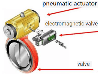
Pneumatic valve is an actuator that uses compressed air to drive and operate the valve. Its opening and closing speed is relatively fast. It is often used for fast two-position cut-off and can also be used to adjust flow. Because it mainly relies on air to perform operations, so it has high practicability in flammable and explosive situations, and can be used to control gas, liquid, oil, and various corrosive media. However, there are many changes in the accessories in the pneumatic valve. With different accessories, various different control methods can not be achieved. The user can configure the corresponding valve according to the different work needs of the valve.

1. Pneumatic triplex is the most common accessory in pneumatic valves, and its function can be simply summarized

pneumatic valve structure

pneumatic valve structure

as: filtration + decompression + oil mist. Among them, the pressure reducing valve is a necessary accessory. The pneumatic valve of any function must be configured. Its function is to give the pneumatic valve a standard power source pressure, the standard value is 0.4-0.7MPa. The pressure reducing valve is a valve that reduces the inlet pressure to a certain required outlet pressure through adjustment, and relies on the energy of the medium itself to automatically maintain a stable outlet pressure. a. The role of the two-piece (filter, pressure reducing valve): complete the filtering and pressure-reducing function of the compressed instrument air b. The role of the three-piece (filter, pressure reducing valve, oil mist device): complete the function of the compressed instrument air Filtering and decompression function, and lubricate the air.

2. The pneumatic solenoid valve can also be called a directional control valve. For two-position valves that only need to be opened and closed, the solenoid valve is a necessary configuration. The solenoid valve achieves the on/off control of the pneumatic valve through excitation/demagnetization. Solenoid valves are often used to switch valves, and control the on and off of the air source and air circuit through voltage signals to control the opening and closing of the valve. Definition: A valve that uses an electromagnet to control the spool movement generally realizes the opening and closing of the valve by controlling the movement process of the pneumatic actuator.

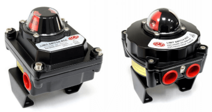
3. The valve limit switch, also called the travel switch, can also be called the echo device. It is a field instrument for

Limit switch-valve

Limit switch-valve

detecting valve status in the automatic control system. It is used to output the open or closed position of the valve as a switch (contact) signal, which is accepted by the program controller or the computer searches for sampling, and executes the next program after confirmation. The product can also be used for interlocking protection of important valves in the system and remote alarm indication. If you want to grasp the valve position status of the two-position valve, the valve limit switch is an effective configuration, which is an electrical switch used to indicate and feedback the limit position of the mechanical equipment.

4. Valve positioner, it is a necessary configuration for pneumatic control valves. The valve positioner can be used to control the position of the valve at any opening degree. It uses the valve stem displacement signal as the input feedback measurement signal and the controller output signal as the setting Signal, compare, when there is a deviation between the two, change its output signal to the actuator, make the actuator act, and establish a one-to-one correspondence between the valve stem displacement times and the controller output signal.
Note: If it is a regulating valve controlled by a safe condition, a solenoid valve must also be configured. The solenoid valve is used to force the valve to be in a safe valve position under unexpected conditions.

For large-capacity cylinder valves, in order to speed up the valve action, the pilot valve must also be configured. The role of the pilot valve is to drive the pilot valve with a small gas signal to switch the atmospheric pipeline, so that the cylinder valve has a better performance. There are many types of pilot valves for fast charging/discharging gas circuits, which should be selected according to the specific needs of pneumatic valves.

If the valve position to be mastered is a regulating valve, a valve opening transmitter must be installed, which can feed back the opening signal of the valve at any position. Due to the requirements of the equipment and technology, the valve may open normally, slowly close, or slowly open, and normally close, then a pneumatic damper is required. The damper is to control the amount of air flow through and adjust to achieve the required valve action speed.

Related products: wafer butterfly valve; lug butterfly valve; double flange butterfly valve;
Double eccentric butterfly valve

The difference and application of stainless steel 430, 304, 316

Stainless steel 430, 304,316 are the material of valve body, valve stem/shaft, or valve disc/plate.

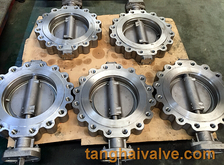
lug type butterfly valve body

lug type butterfly valve body

430 ferritic stainless steel containing more than 12% chromium can prevent oxidation caused by natural factors. It is called stainless steel. It belongs to 430 ferritic stainless steel. It has low thermal expansion rate, excellent formability and oxidation resistance. The code name in JIS is 430, so it is also called 430 stainless steel.

Application of 430 ferritic stainless steel: 430 stainless steel (16Cr) is often used to make household appliances, heat-resistant appliances, burners, home appliances, class 2 tableware, kitchen sinks, exterior decoration materials, bolts, nuts, CD rods, screens .

The difference between 430 stainless steel and 304, 316 austenitic stainless steel: 430 stainless steel and 304, 316 austenitic stainless steel are identified by spectral analysis and chemical element analysis. Both 304 and 316 are austenitic stainless steels. 316 is made of 304 stainless steel with molybdenum added. Therefore, 316 stainless steel has much better seawater and rust resistance than 304.
The difference between 304, 316 and 430 lies in the rust resistance. In addition to chromium, 304 and 316 also contain elements such as nickel and molybdenum, and are non-magnetic. Therefore, the rust resistance of 304/316 austenitic stainless steel is better than 430 stainless steel is much better and the price is much higher. To

Can the 430 stainless steel magnet hold it? 304 and 316 are not magnetic and cannot be attracted by magnets. Generally, it does not generate heat in a high-voltage electromagnetic environment, so it is used more. Martensitic and 430 ferritic stainless steel, precipitation hardening stainless steel are magnetic, and magnets can attract them.

Will 430 stainless steel rust? 430 stainless steel cannot resist the oxidation caused by chemicals in the air. Because there are more and more acidic chemicals in the air, 430 stainless steel will still be oxidized (rusted) due to unnatural factors after being used for a period of time.

Which is better, 430 stainless steel or 304? 304 austenitic stainless steel has excellent corrosion resistance and no magnetism. Relatively speaking, austenitic stainless steel 304 is better than 430 ferritic stainless steel.

How expensive is 430 stainless steel compared to 304? Generally speaking, austenitic stainless steel 304 is twice as expensive as 430 stainless steel.

TH Valve is a professional manufacturer of butterfly valvegate valvecheck valveglobe valveknife gate valve, ball valve with API, JIS, DIN standard, used in Oil, Gas, Marine industry, Water supply and drainage, fire fighting, shipbuilding, water treatment and other systems, with Nominal Diameter of DN50 to DN1200, NBR/EPDM/VITON, Certificates & Approvals: DNV-GL, Lloyds, DNV, BV, API, ABS, CCS. Standards: EN 593, API609, API6D

Related news/knowledge:
Stainless steel vertical check valve;
Wafer type double disc swing check valve introduction;
Pneumatic ball valve model preparation method;
Pneumatic butterfly valve model name coding method