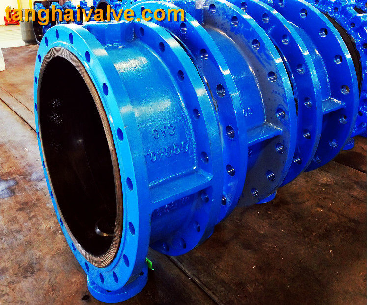
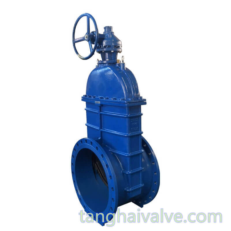
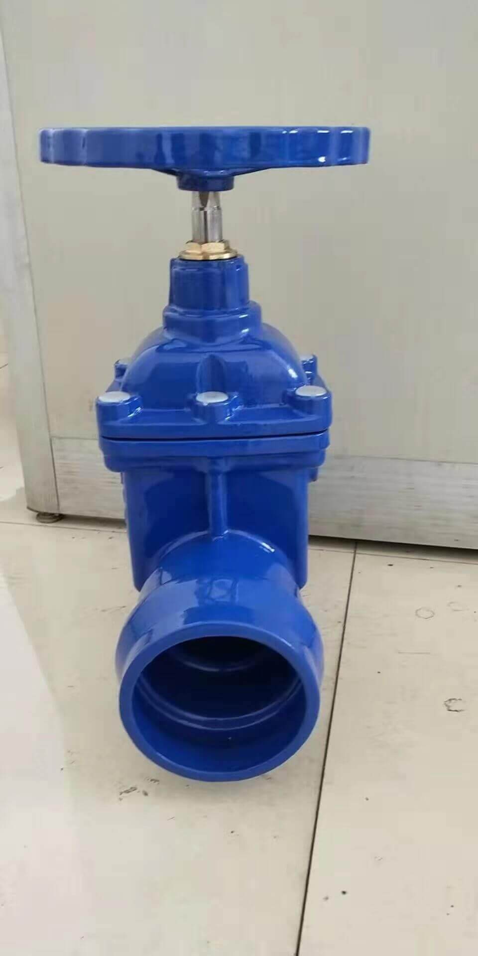
Resilient seated socket end gate valve
GATE VALVE-resilient seated SOCKET END
Standard: EN1074; EN1171
Socket ended resilient seated wedge gate valve-ductile iron (1)
CAST IRON / DUCTILE IRON GATE VALVE SOCKET END
NON RISING STEM
Pressure: PN10 / PN16
Connection ends: Socked ends, for PVC pipes, uPVC pipes
FACE TO FACE: ACCORDING TO BS, DIN, ANSI, AWWA, SABS STANDARD ETC.
BODY:CAST IRON/DUCTILE IRON
BONNET:CAST IRON/DUCTILE IRON
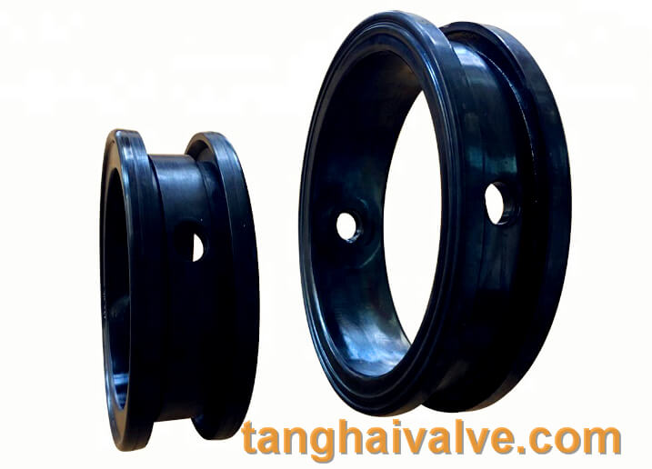
WEDGE:CAST IRON/DUCTILE IRON, fully vulcanized with EPDM rubber
STEM: SS/BRASS
Coating: fusion bonded expoxy coating
The opening and closing part of the socket gate valve is a gate. The movement direction of the gate is perpendicular to the direction of the fluid. The gate valve can only be fully opened and fully closed, and cannot be adjusted or throttled. The gate has two sealing surfaces. The two sealing surfaces of the most commonly used mode gate valve form a wedge. The wedge angle varies with valve parameters, usually 50, and 2°52′ when the medium temperature is not high. The gate of the wedge gate valve can be made into a whole, called a rigid gate; it can also be made into a gate that can produce slight deformation to improve its manufacturability and compensate for the deviation of the sealing surface angle during the processing. The plate is called an elastic gate.
Socket gate valve can be divided into wedge gate valve and parallel gate valve according to the sealing surface configuration. The wedge gate valve can be divided into: single gate, double gate and elastic gate; parallel gate valve can be divided into It is single gate type and double gate type. According to the thread position of the valve stem, it can be divided into two types: rising stem gate valve and non-rising stem gate valve.
When the socket gate valve is closed, the sealing surface can only rely on the medium pressure to seal, that is, rely on the medium pressure to press the sealing surface of the gate against the valve seat on the other side to ensure the sealing of the sealing surface, which is self-sealing. Most gate valves use forced sealing, that is, when the valve is closed, the gate must be forced against the seat by external force to ensure the sealing performance of the sealing surface.
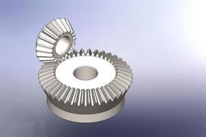
The gate of the socket gate valve moves linearly with the valve stem, which is called rising stem gate valve (also called rising stem gate valve). Usually there is a trapezoidal thread on the lifting rod, through the nut on the top of the valve and the guide groove on the valve body, the rotary motion is changed into linear motion, that is, the operating torque is changed into operating thrust.
When the valve is opened, when the lifting height of the gate is equal to 1:1 times the valve diameter, the fluid passage is completely unblocked, but this position cannot be monitored during operation. In actual use, the apex of the valve stem is used as a mark, that is, the position where it cannot be opened, as its fully open position. In order to take into account the locking phenomenon of the temperature change, it is usually at the top position of the opening, and then rewind 1/2-1 turn as the position of the fully open valve. Therefore, the fully open position of the valve is determined by the position of the gate (that is, the stroke).
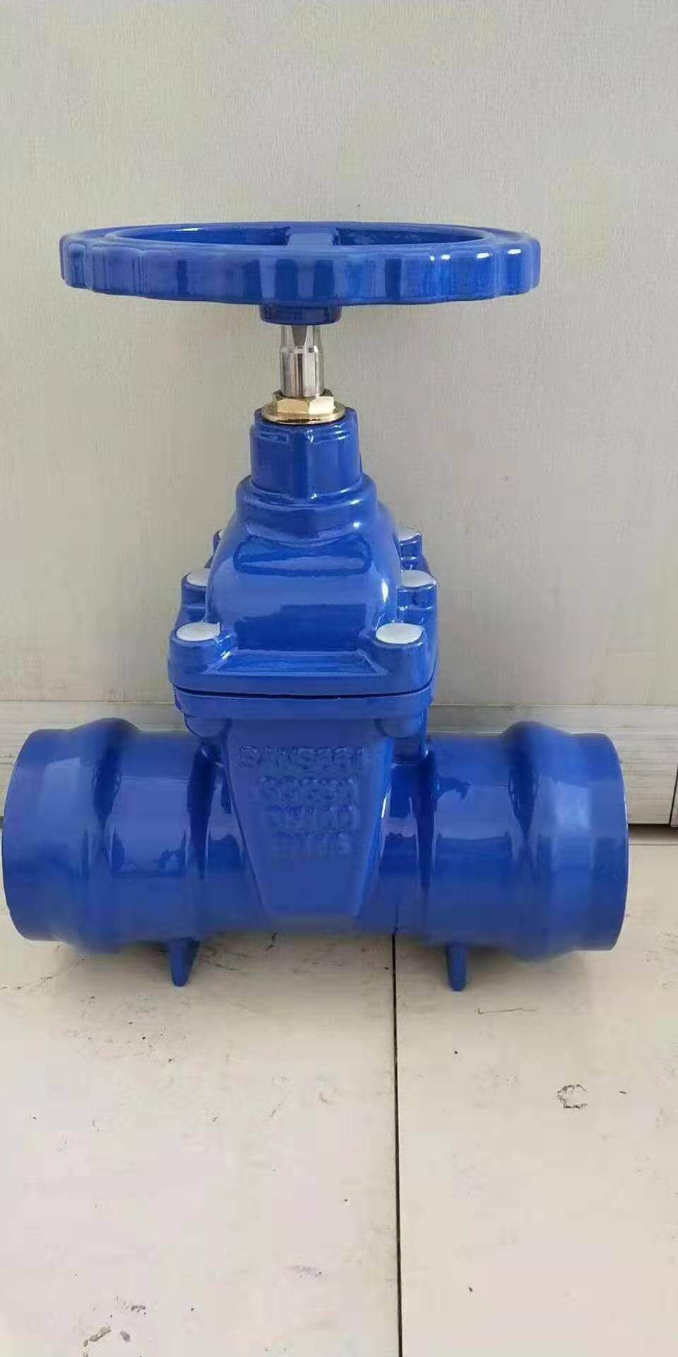
Socket ended resilient seated wedge gate valve-ductile iron (2)
In some gate valves, the stem nut is set on the gate, and the rotation of the handwheel drives the rotation of the valve stem to lift the gate. This kind of valve is called a rotating stem gate valve or a dark stem gate valve.
advantage:
The fluid resistance is small, and the sealing surface is less brushed and corroded by the medium.
It is easier to open and close.
The flow direction of the medium is not restricted, does not disturb the flow, and does not reduce the pressure.
The shape is simple, the length of the structure is short, the manufacturing process is good, and the scope of application is wide.
Disadvantages:
It is easy to cause erosion and scratches between the sealing surfaces, which makes maintenance difficult.
The overall size is large, opening requires a certain amount of space, and the opening and closing time is long.
The structure is more complicated.
The types of socket gate valves can be divided into wedge gate valves and parallel gate valves according to the sealing surface configuration. Wedge gate valves can be divided into: single gate type, double gate type and elastic gate type; parallel gate type Gate valves can be divided into single gate type and double gate type. Divided according to the thread position of the valve stem, it can be divided into two types: open stem gate valve and dark stem gate valve.
Matters needing attention in installation and maintenance
Handwheels, handles and transmission mechanisms are not allowed to be used for lifting, and collisions are strictly prohibited.
The double gate valve should be installed vertically (that is, the valve stem is in the vertical position and the handwheel is at the top).
The gate valve with bypass valve should be opened before opening (to balance the pressure difference between inlet and outlet and reduce the opening force).
The gate valve with transmission mechanism should be installed according to the product manual.
If the valve is frequently opened and closed, lubricate at least once a month.
Structural features:
The general gate valves used on the market for a long time generally have water leakage or rust. The company introduces the elastic seat seal gate valve produced by European high-tech rubber and valve manufacturing technology, which overcomes the defects of poor sealing and rust of general gate valves. The sealing gate valve uses the compensation effect of the elastic gate plate to produce a small amount of elastic deformation to achieve a good sealing effect. The valve has the obvious advantages of light switch, reliable sealing, good elastic memory and service life. It can be widely used as a regulating and intercepting device on the pipelines of tap water, sewage, construction, petroleum, chemical industry, food, medicine, textile, electric power, shipbuilding, metallurgy, energy system, etc.