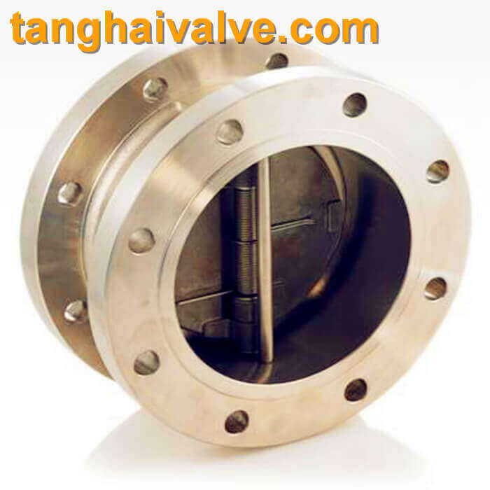
Dual plate check valve in marine valve
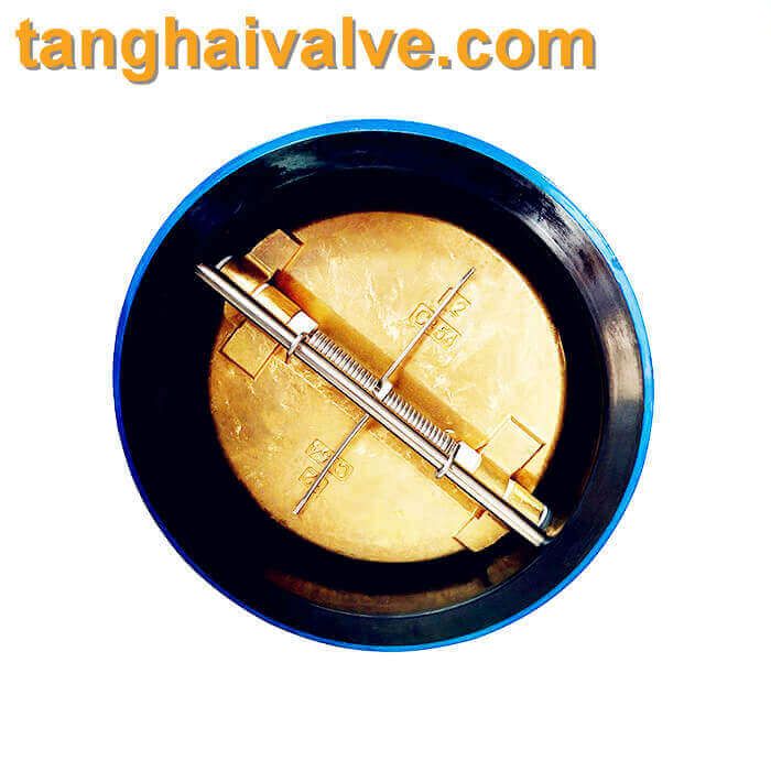
A double plate check valve, also known as a dual plate check valve or wafer check valve, is a type of non-return valve commonly used in various fluid systems on ships. It is designed to allow fluid to flow in one direction while preventing backflow, ensuring that the fluid flow is unidirectional. Here are some key features and details about double plate check valves used in ship valves:
 Key Features of Double Plate Check Valves
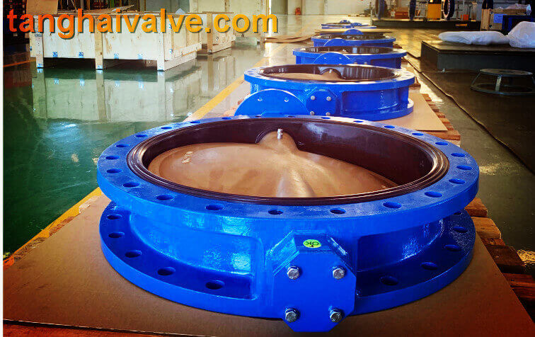
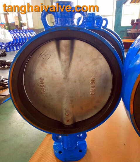
1,Dual Plates: The valve has two spring-loaded plates or discs that open when fluid flows in the desired direction and close when there is a reversal of flow. This design ensures a quick response to changes in flow direction.
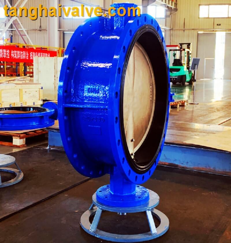
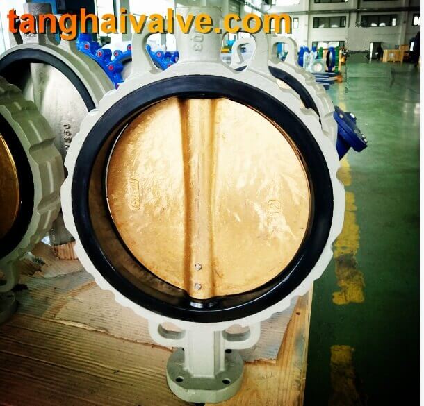
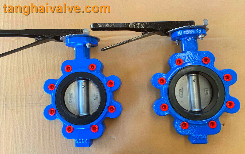
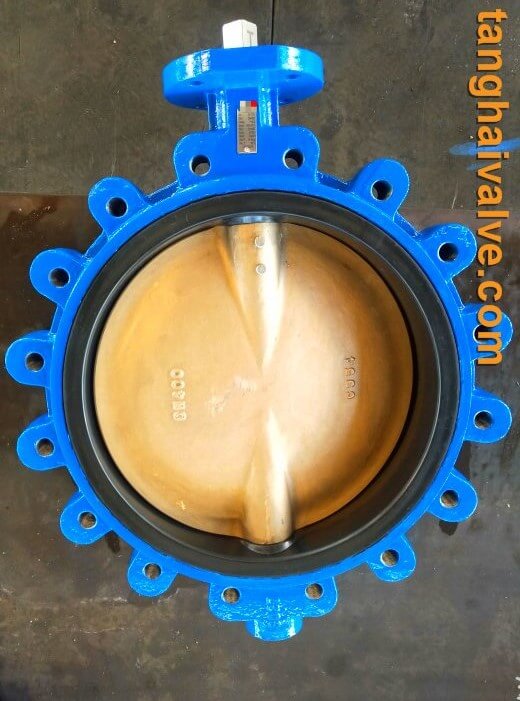
2,Wafer Type Design: These valves have a compact and lightweight wafer design, making them easy to install between flanges in a pipeline. They occupy less space compared to other types of check valves.
3,Non-Slam Closure: The spring-loaded mechanism ensures a non-slam closure, reducing the risk of water hammer, which can cause damage to the piping system.
4,Low Pressure Drop: The dual plate design offers minimal resistance to flow, resulting in a low-pressure drop across the valve.
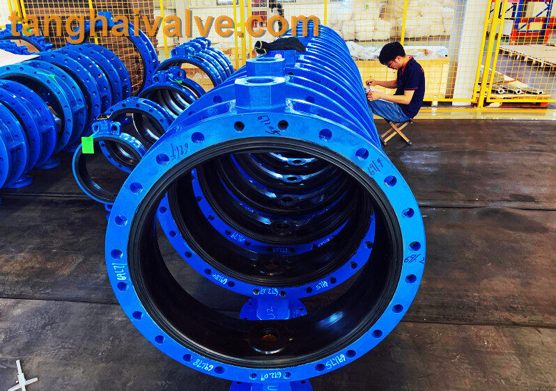
5,Material Options: These valves are available in various materials such as stainless steel, cast iron, and other alloys to suit different types of fluids and environmental conditions, including seawater applications.
6,Versatility: Suitable for a wide range of applications including ballast systems, cooling systems, fuel systems, and bilge systems on ships.
 Advantages in Marine Applications
1,Space-Saving: The compact design is particularly advantageous in the confined spaces typically found in marine engine rooms and other shipboard locations.
2,Durability: Marine environments are harsh, and the materials used in these valves are selected for their corrosion resistance and durability.
3,Maintenance: Double plate check valves are designed for easy maintenance, which is critical in marine operations where downtime needs to be minimized.
4,Efficiency: By preventing backflow and ensuring a unidirectional flow, these valves contribute to the efficiency and reliability of the ship’s fluid systems.
Common Uses on Ships
Ballast Water Systems: Ensuring the correct flow direction in ballast water management, crucial for the stability and balance of the ship.
Cooling Water Systems: Used in engine cooling systems to ensure the proper flow of seawater or freshwater for cooling purposes.
Fuel Systems: Preventing backflow in fuel lines, which is critical for the safe and efficient operation of ship engines.
Bilge Systems: Ensuring the proper discharge of bilge water and preventing backflow into the bilge.
Installation and Maintenance Tips
Proper Alignment: Ensure the valve is correctly aligned with the flow direction indicated on the valve body during installation.
Regular Inspection: Periodic inspection and maintenance are essential to ensure the valve operates correctly and to prevent potential failures.
Material Compatibility: Select the appropriate material for the valve based on the specific application and the type of fluid being handled to avoid corrosion and other issues.
In summary, double plate check valves are a critical component in shipboard fluid systems, providing reliable performance, efficiency, and ease of maintenance, which are essential for the safe and effective operation of maritime vessels.
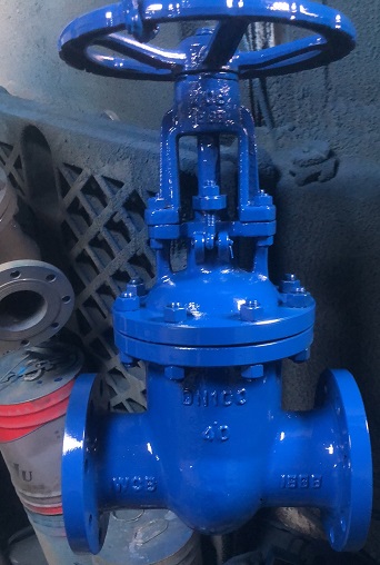
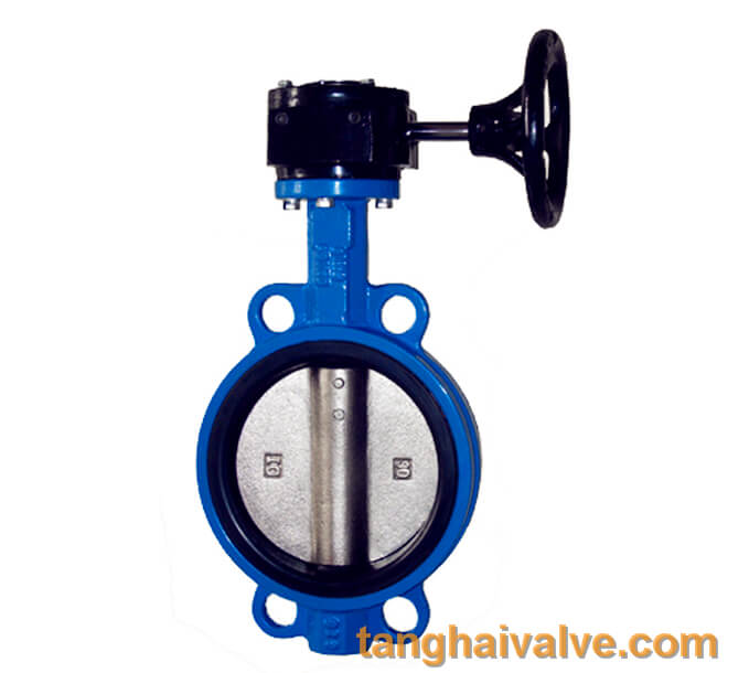
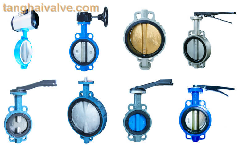
Tianjin Tanghai Valve Co., Ltd. is a professional marine valve manufacturer, including butterfly valve, check valve, gate /Knife gate valve. We have certificates: CE, ISO, BV, DNV foundry and products approval. Now we have our own independent R & D, manufacturing, assembly and warehousing workshops; we have professional pre-sale and after-sale technical support and perfect services. Below is our wafer butterfly valve of marine valves,if you need to check more information, please click here:https://www.tanghaivalve.com/wafer-type-butterfly-valve-th-btv-aw/.
Please contact us if you need more support, please contact us freely: info@tanghaivalve.com.
We are committed to “Build a top valve enterprise; Be a reliable partner!”Friends from all over the world are welcome to visit us for evaluation, guidance, and orders!