Spur gear is a classification of gears. According to the relative position and tooth direction of a pair of gear axes (whether the two circles are parallel), it can be divided into plane gear rotation and space gear rotation; according to
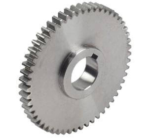
Spur gear
the working conditions of the gears, it can be divided into open transmission and closed transmission; according to gear teeth or tooth profile. The gear is divided into straight teeth, helical teeth, herringbone teeth, or straight teeth, curved teeth, as per the shapes.
The code name is 4 for valve drive mode. see details at: https://www.tanghaivalve.com/valve-model-establishment-and-meaning/
Unit One , valve type (code name):
| butterfly valve |
safety valve |
Diaph-ragm valve |
ball valve |
gate valve |
check valve |
plug valve |
Pressure reducing valve |
globe valve |
filter |
Disch-arge valve |
| D |
A |
G |
Q |
Z |
H |
X |
Y |
J |
GL |
FL |
Unit two, valve drive mode (code name):
| drive mode |
Electro-magne-tism |
Electro-magnetic hydraulic |
Electro-hydraulic |
tur-bine |
Spur gear |
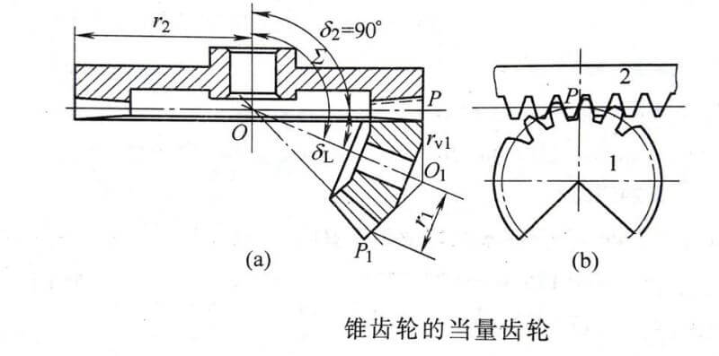
Bevel gear |
pneu-matic |
Hydr-aulic |
Gas-hydr-aulic |
elec-tric |
han-dle |
Hand-wheel |
| code |
0 |
1 |
2 |
3 |
4 |
5 |
6 |
7 |
8 |
9 |
|
|
Unit three, valve connection method (code name):
| connection |
internal thread |
external thread |
two different connections |
flange |
welding |
wafer |
clamp |
ferrule |
| code |
1 |
2 |
3 |
4 |
6 |
7 |
8 |
9 |
Classification
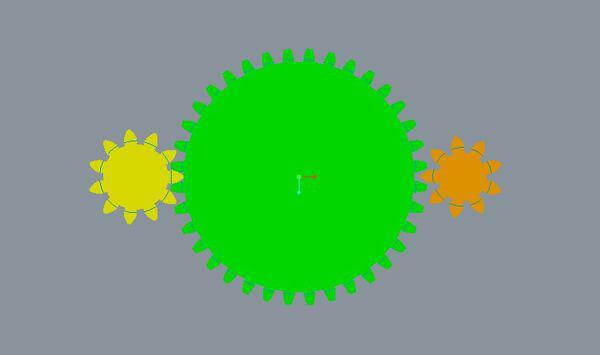
Straight cylinder/spur gear
Meshing mode: external meshing, internal meshing, gear and rack
Basic characteristics: The tooth profile contact line is a straight line parallel to the axis. A pair of tooth profiles enter or exit the mesh at the same time along the tooth width, which is likely to cause shock and noise, and the transmission stability is poor.
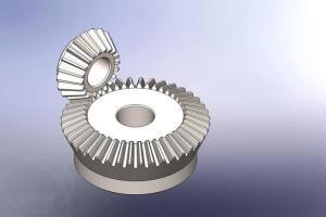
Straight bevel gear:
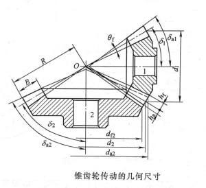
Pitch cone, index cone, tooth tip cone, tooth root cone, base cone; used for transmission between intersecting two shafts, the gear teeth are distributed along the cone surface, and the size of the starting gear teeth gradually decreases toward the cone tip.
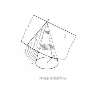
In order to enable the gear to rotate in both directions, the tooth profile on both sides of the gear tooth is composed of involute surfaces with the same shape and opposite directions. The names and symbols of each part are: addendum circle, tooth root circle, tooth Slot, tooth thickness, tooth pitch, modulus m, index circle d, tooth top and tooth root, top clearance
Gears are divided into spur gears, helical gears, herringbone gears, and curved gears according to the shape of the tooth line. The spur gears are gears whose teeth are parallel to the axis.
Surveying method:
The spur gear is one of the most common gears in actual production and use. Damage is inevitable during use. Therefore, it is necessary to make a new gear that is the same as the original one. For various reasons, the customer cannot provide the required spur gear. In order to ensure the normal use of the processed products, the gear drawings need to be accurately surveyed and mapped. The surveying and mapping work is a complicated task. Since there are few data on the surveying and mapping of spur gears, it is naturally inconvenient to consult. The work experience and methods of surveying and mapping spur gears in several actual production are summarized by the operation. The introduction is as follows:
First of all, although there are many parameters and dimensions of spur gears, the standard system of various gears stipulates the modulus or diameter pitch as the calculation basis for other parameters and the dimensions of each part. Therefore, the surveying and mapping work should make every effort to accurately determine the size of the modulus or the diametral pitch. At the same time, the pressure angle is the basic parameter to determine the tooth profile, and accurate determination is equally important.
Secondly, we need to understand the usage and production country of the gear being surveyed, so that we can estimate the standard system adopted by this gear. Generally speaking, China, Japan, Germany, France, Czech Republic, and the former Soviet Union all adopt the modular system. You can also observe the tooth profile of the gear. If the tooth profile is curved and the bottom of the tooth groove is narrow and arc-shaped, it can be preliminarily judged as a modular system. The standard pressure angle is mostly 20 degrees; the United States and the United Kingdom adopt diameter control, and the standard pressure angles are 14.5 degrees and 20 degrees. Observing that the tooth profile is relatively straight and the bottom of the tooth groove is wider and the arc is small, it can be preliminarily judged as the diameter control. The pressure angle is 14.5 degrees. You can also use gear hobs or standard rack samples to determine which pressure angle is. If you know the above conditions, you can actually survey and map:
(1) Method of measuring the diameter of the addendum circle Dm
First count the number of teeth Z of the gear, and then use a vernier caliper to measure the diameter Dm of the addendum circle. If it is determined that the gear is a modular standard tooth profile, its modulus:
m = Dm/Z+2
If it is determined that the gear is a standard tooth profile with diameter control, its diameter pitch is
Dp=25.4*(Z+2)/ Dm
However, it should be noted that if the number of teeth of the gear is even, it can be directly measured; if the number of teeth is odd, the measured size is not the addendum diameter Dm, but two teeth from the tip of a tooth to the opposite tooth space. The distance D between the intersection of the face and the addendum circle is smaller than the diameter of the addendum circle. Usually, Dm is multiplied by the correction coefficient k to get the addendum circle diameter D, namely:
Dm=k*D
In practice, the diameter of the addendum circle calculated by the odd-numbered gear addendum circle diameter correction coefficient k (Table 1) is generally small. The diameter of the addendum circle calculated using the corrected correction coefficient k (Table 2) according to the above formula is more Close to the real value, Table 2 is more accurate than Table 1, and the number of teeth is finer, for reference.

fig.1-Odd tooth gear Addendum circle diameter Correction coefficient K
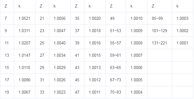
fig.2-Correction coefficient after correction k
If the odd-numbered gear is not a gear shaft but has a hole, you can also measure the inner hole diameter d and the distance H from the hole wall to the tooth tip, and get the tooth tip circle diameter by the following formula:
Dm=2*H+d
(2) Method of measuring the height of the tooth
When the gear is inconvenient to measure the diameter of the addendum circle due to large modulus, tooth punching, etc., the full height h of the tooth can be measured to determine the modulus or diametral pitch. The total tooth height h can be measured with the depth tail needle of a vernier caliper, and other depth measuring tools are also available, depending on the site conditions; if the gear has a hole, the tooth total height h can be obtained indirectly by measuring the inner hole wall to the tooth tip and tooth root The subtraction of the distance is the total tooth height h, and the modulus or diametral pitch is calculated as follows:
m=h/2f+c Dp=25.4*(2f+c)/h
f:: Addendum height coefficient c: Radial clearance coefficient
f, c can be found by checking the gear standard system parameter table[3]
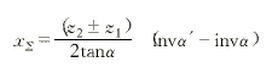
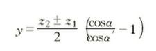
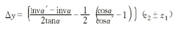
(3) Method of measuring center distance A
When the gear teeth are sharp, worn, or rolled, the above two methods cannot be measured. At this time, we can ask the customer to provide the center distance A of the two paired gears and the number of teeth of the two gears. These are easy to do. Calculate the modulus or diametral pitch as follows:
m=2*A/Z1+Z2 Dp=25.4*(Z1+Z2)/2*A
Z1, Z2: Number of teeth of matched gear
The modulus or diametral pitch calculated by any one of the three methods is compared with the standard modulus or diametral pitch series, and the closest one is fine.
The above are the commonly used methods for surveying and mapping spur gears in actual work. It is best to use two methods to check each other, so that the determined modulus or diameter section is more accurate, and the surveying and mapping work is basically completed. Special attention: The above surveying and mapping methods are carried out under the condition that we can pre-determine or investigate the standard system adopted by the gear. If the gear’s “all conditions are unknown”, the above methods can only be referred to, and then comprehensively judged by other means. It is believed that the above several surveying methods will be helpful to colleagues who have just joined the work soon or for the first time to survey and map spur gears. It is worth referring to.
TH Valve is a professional manufacturer of butterfly valve, gate valve, check valve, globe valve, knife gate valve, ball valve with API, JIS, DIN standard, used in Oil, Gas, Marine industry, Water supply and drainage, fire fighting, shipbuilding, water treatment and other systems, with Nominal Diameter of DN50 to DN1200, NBR/EPDM/VITON, Certificates & Approvals: DNV-GL, Lloyds, DNV, BV, API, ABS, CCS. Standards: EN 593, API609, API6D
Related news/knowledge:
what is bevel gear?
What is the positive transmission of gears
Form and types of Gear transmission
What is the gear modification coefficient