Precautions for installation and use of NRS gate valve
NRS gate valve means non-rising stem gate valve; RS gate valve means rising stem gate valve.
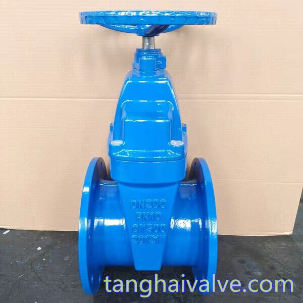
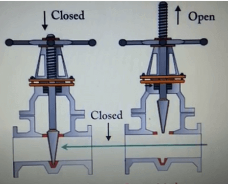
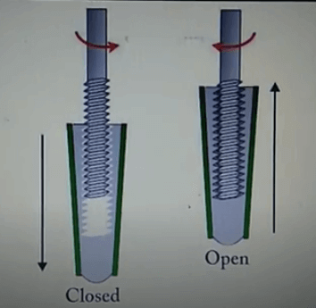
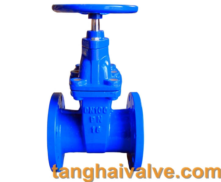
Gate valves can be divided into RS gate valves and NRS gate valves according to their appearance structure. This article mainly introduces the NRS gate valve. In the structure of the NRS gate valve, the stem nut is placed inside the valve body and fixed on the gate plate. Through the rotation of the valve stem, the valve stem nut drives the gate plate to move up and down to complete the opening and closing.
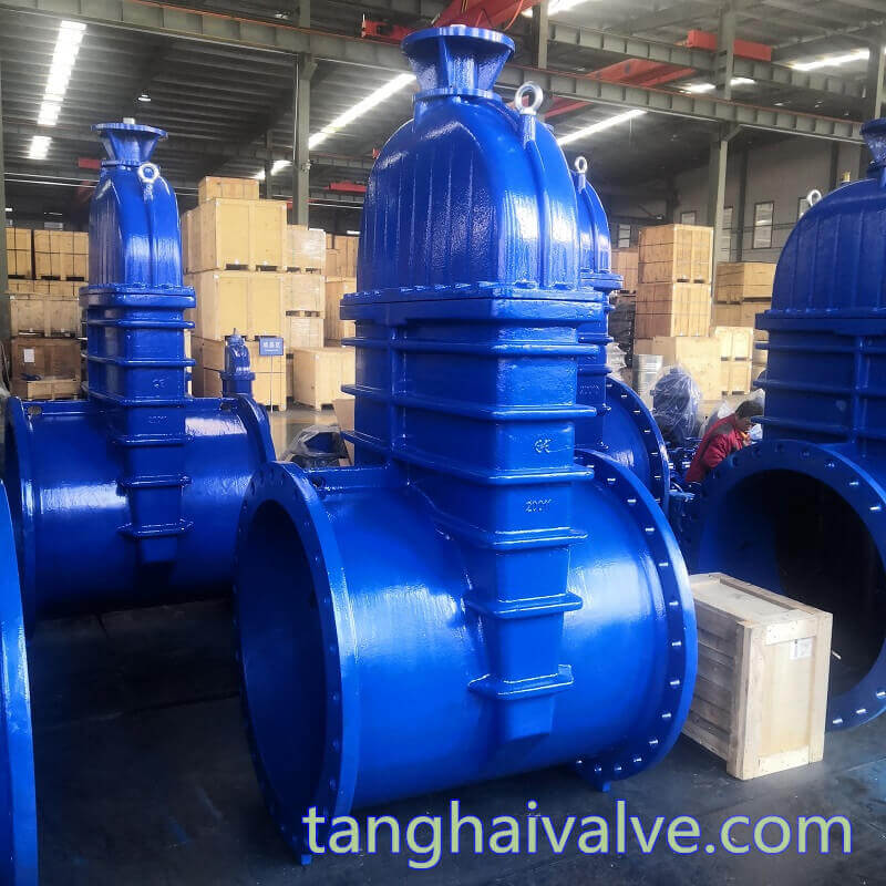
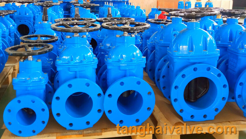
DN1000-DIN-F5-NRS gate valve-IS&Y (6)
The trapezoidal thread used in the drive of the concealed stem gate valve is located inside the valve body, so it is not affected by the external environment, but it is easily corroded by the medium circulating in the pipeline, and cannot be directly lubricated, which will damage the valve stem over time. Because the valve stem is located in the valve body, the opening degree of the concealed stem gate valve cannot be directly observed, and an indicator device is required.
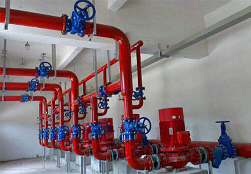
The concealed stem gate valve requires a small operating space and is suitable for occasions with limited locations and dense pipelines, such as ships and underground pipelines. So what should be paid attention to during the installation and use of the concealed stem gate valve?
1. Before installation, you must carefully check the various standards of the concealed stem gate valve and whether the diameter meets the requirements for use; pay attention to the valve during transportation to avoid bumps. Before installing the concealed stem gate valve, remove the dirt in the valve body.
2. During installation, the concealed stem gate valve can be directly installed on the pipeline according to the connection method and installed according to the used position. Under normal circumstances, it can be installed at any position of the pipeline, but for future operation and maintenance considerations, choose an appropriate location for installation. The concealed stem gate valve should pay attention to the tightness during installation to prevent leakage and affect the normal operation of the pipeline.
3. The NRS gate valve should always be kept clean during use, and the transmission thread must be regularly lubricated. When a fault is found, it should be stopped immediately to find out the cause and clear the fault.
4. The concealed stem gate valve uses a hand wheel, do not use levers or other tools to avoid damaging the valve parts. Turn the handwheel clockwise to close, and vice versa to open. The dark stem gate valve should be used reasonably to ensure the correct use method and means.
5. The NRS gate valve stored for a long time should be checked regularly. The processing surface that is often
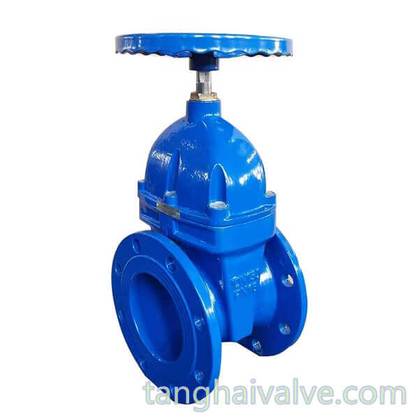
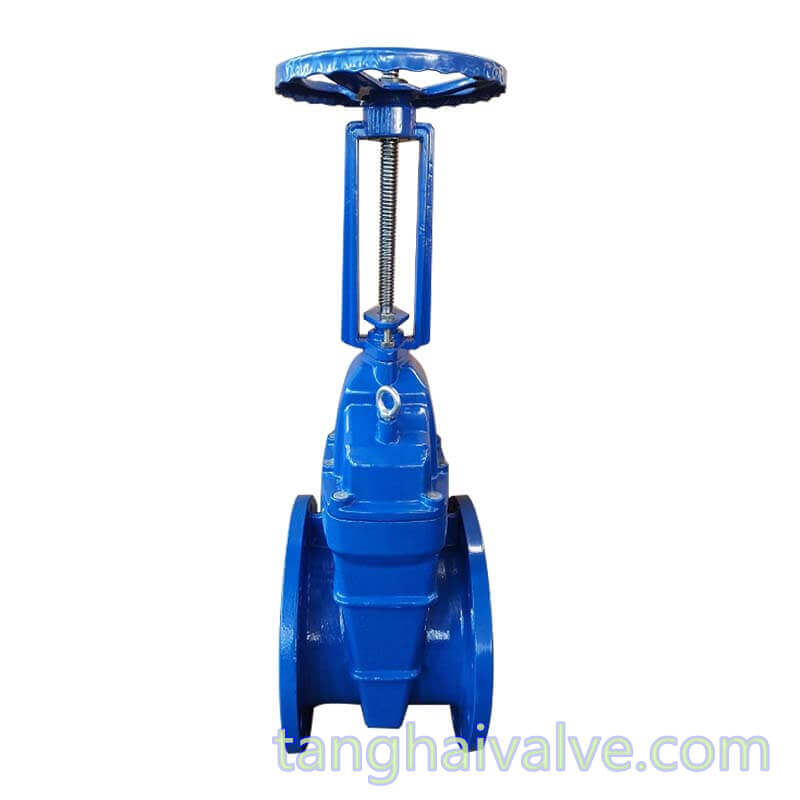
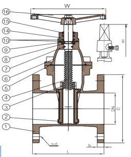
DIN-F4-BB-NRS-soft seated-wedge gate valve-DN100-PN16-copper holding ring-handwheel (3)
exposed should be kept clean, cleaned of dirt, and stored neatly in a ventilated and dry place indoors. It is strictly forbidden to stack or store in the open air.
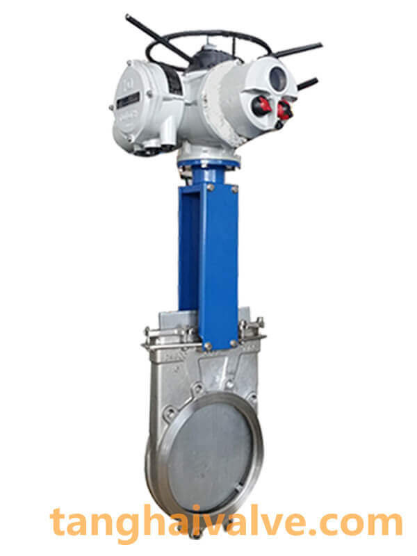
TH Valve is a professional manufacturer of butterfly valve, gate valve, check valve, globe valve, knife gate valve, ball valve with API, JIS, DIN standard, used in Oil, Gas, Marine industry, Water supply and drainage, fire fighting, shipbuilding, water treatment and other systems, with Nominal Diameter of DN50 to DN1200, NBR/EPDM/VITON, Certificates & Approvals: DNV-GL, Lloyds, DNV, BV, API, ABS, CCS. Standards: EN 593, API609, API6D
Related news/knowledge:
Difference between NRS gate valve and RS gate valve;
Non-rising stem(NRS) and rising stem(RS) gate valve;
structures and differences of Non-rising stem(NRS) and rising stem(RS) gate valve;
Installation method and precautions of check valve