Gate valve model meaning and representation method
Gate valve model representation method | Gate valve model meaning
Explanation of the meaning of the gate valve model:
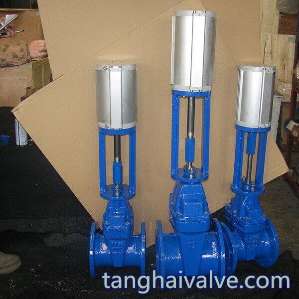
pneumatic gate valve (3)
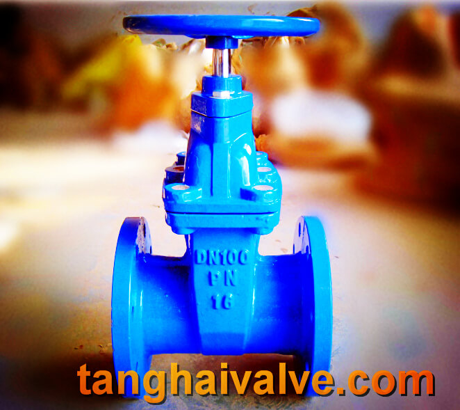
Gate valve is one of the more common types of shut-off valves. It is generally suitable for full-open or full-close two-position operation control. It is mainly used to close the medium in the pipeline. It is usually called a cut-off valve or a blocking valve. With the increase in demand for valves and the expansion of demand in the machinery industry, gate valves have become an indispensable part of modern industrial control systems. For more and more complex working conditions and harsh use requirements, the correct selection of gate valve models is related to the adaptability of the pipeline medium and an important guarantee for the safety of the working conditions. The user should have a detailed understanding of the method of preparing the gate valve model to avoid problems such as selecting the wrong model, placing the wrong order, and unclear technical parameters resulting in replacement and return.
This compilation method is the representation method of the standard gate valve model in my country. It mainly explains in detail the additional conditions of the gate valve, drive mode, connection form, structural feature, sealing material, pressure level and valve body material. Other customized or special product models are not applicable to this method and need to be explained separately.
The method of formulating and expressing gate valve model:
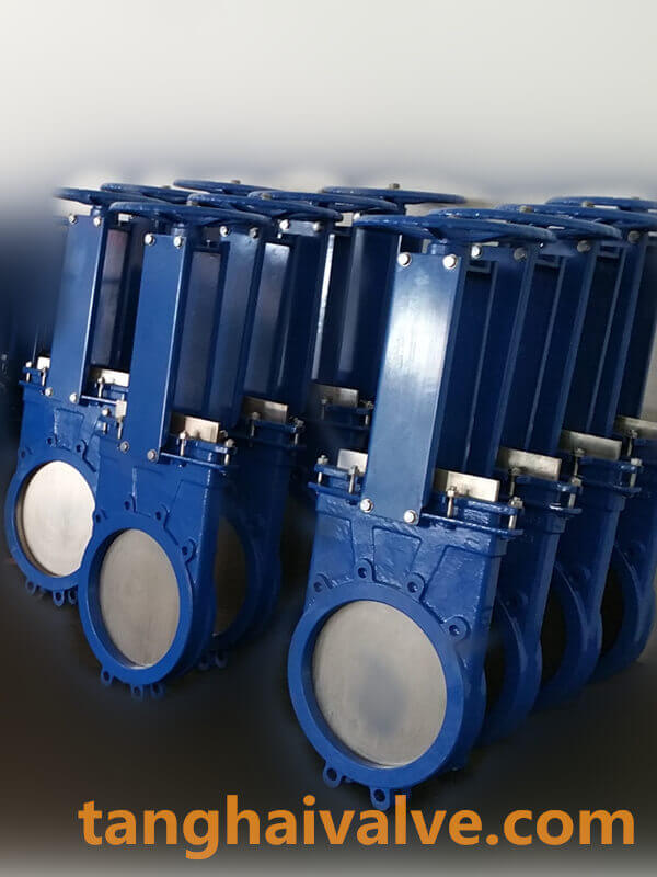
Additional code for gate valve: WZ means bellows gate valve, DZ cryogenic gate valve, NKZ vacuum gate valve, PZ knife gate valve;
Type of gate valve: Z;
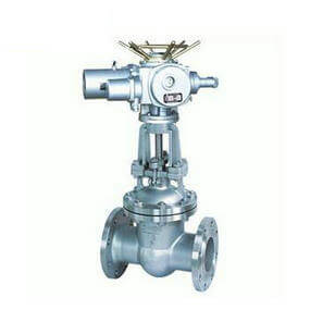
Drive mode: manual without code (usually omitted according to regulations), 2 electro-hydraulic, 3 worm gear, 5-bevel gear transmission, 6 pneumatic, 9-electric;
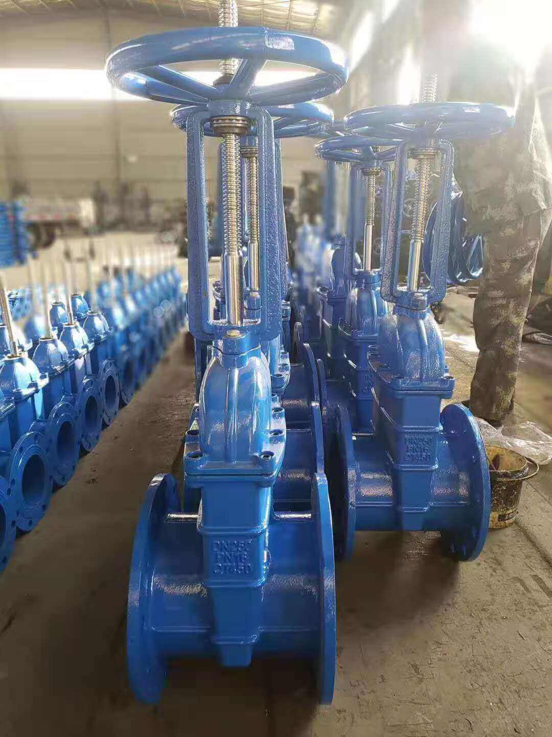
Connection mode: 4 flange connection, 6 welding, 7 pair clip type;
Structural form: 0 elastic gate, 1 open-rod wedge-type single gate, 2-open-rod wedge-type double gate, 3-open-pole parallel single gate, 4-open-pole parallel double gate, 5 concealed Rod wedge single gate, 6 concealed rod wedge double ram, 7 concealed rod parallel single ram, 9 concealed rod parallel double ram;
Sealing material: W valve body is directly processed, T alloy, X rubber, F fluoroplastic, H-Cr stainless steel, Y cemented carbide, M Monel alloy;
Pressure rating: PN1.0-32Mpa, 16=1.6MPA means the pressure is 16 kg, 150LB-1500LB means the American standard pound pressure, 5-63K means the Japanese pressure;
Valve body material: Z-gray cast iron, Q ductile iron, T alloy, C carbon steel, P stainless steel 304, R stainless steel 316, V chromium molybdenum vanadium steel.
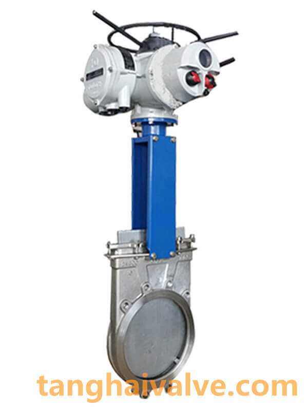
Knife-gate-valve-1-
Example of preparing gate valve model:
PZ973H-16C Electric Wafer Type Knife Gate Valve
1. PZ: stands for knife gate valve;
2. 9: indicates that the transmission mode is electric;
3. 7: The connection method is a clip-on connection;
4. 3: The structure is an open pole parallel single gate;
5. H: The sealing material is stainless steel;
6. 16: Indicates that the nominal pressure is 1.6MPa;
7. C: Indicates that the valve body material is carbon steel.
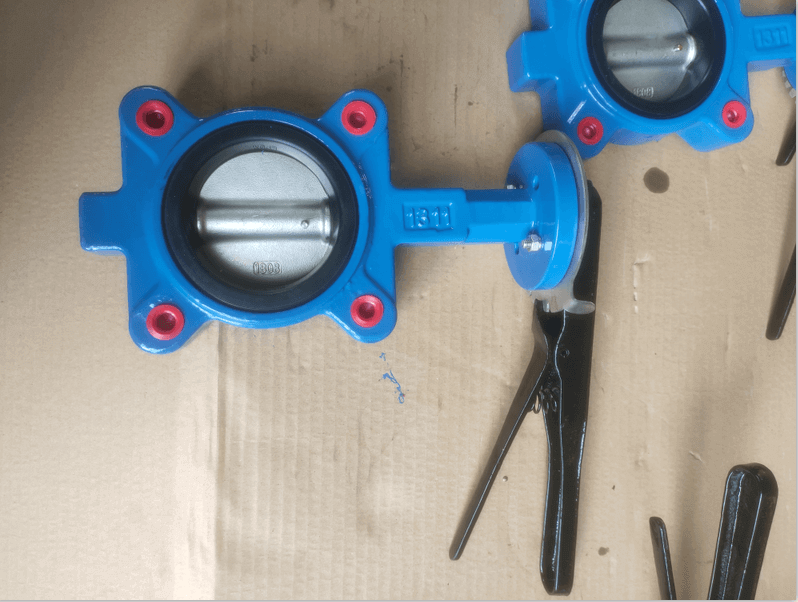
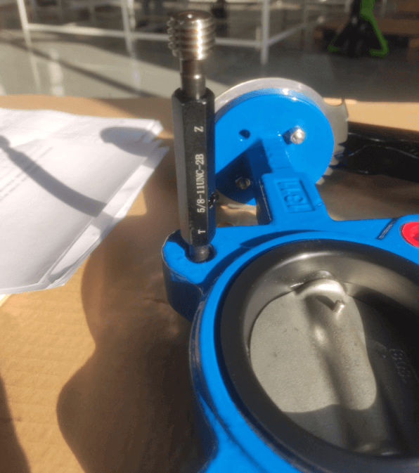
TH Valve is a professional manufacturer of butterfly valve, gate valve, check valve, globe valve, knife gate valve, ball valve with API, JIS, DIN standard, used in Oil, Gas, Marine industry, Water supply and drainage, fire fighting, shipbuilding, water treatment and other systems, with Nominal Diameter of DN50 to DN1200, NBR/EPDM/VITON, Certificates & Approvals: DNV-GL, Lloyds, DNV, BV, API, ABS, CCS. Standards: EN 593, API609, API6D
related news /knowledge:
Representation method of butterfly valve model;
Representation method of electric gate valve model;
Pneumatic gate valve model preparation method;