Tag Archive for: gate valve

Posts

Types and classifications of gate valves

Gate valve, also called plate gate valve, is mainly composed of valve body, bonnet, disc, valve stem, valve seat and sealing packing. It is one of the most common valve types in isolation valves. The main purpose of the gate valve is to cut off the fluid. For this reason, it is usually called a “cut off” valve or a “blocking” valve. The gate valve has many different structural forms, and the sealing element structure used in it is different. According to the structure of the sealing element, it can be divided into several different types.
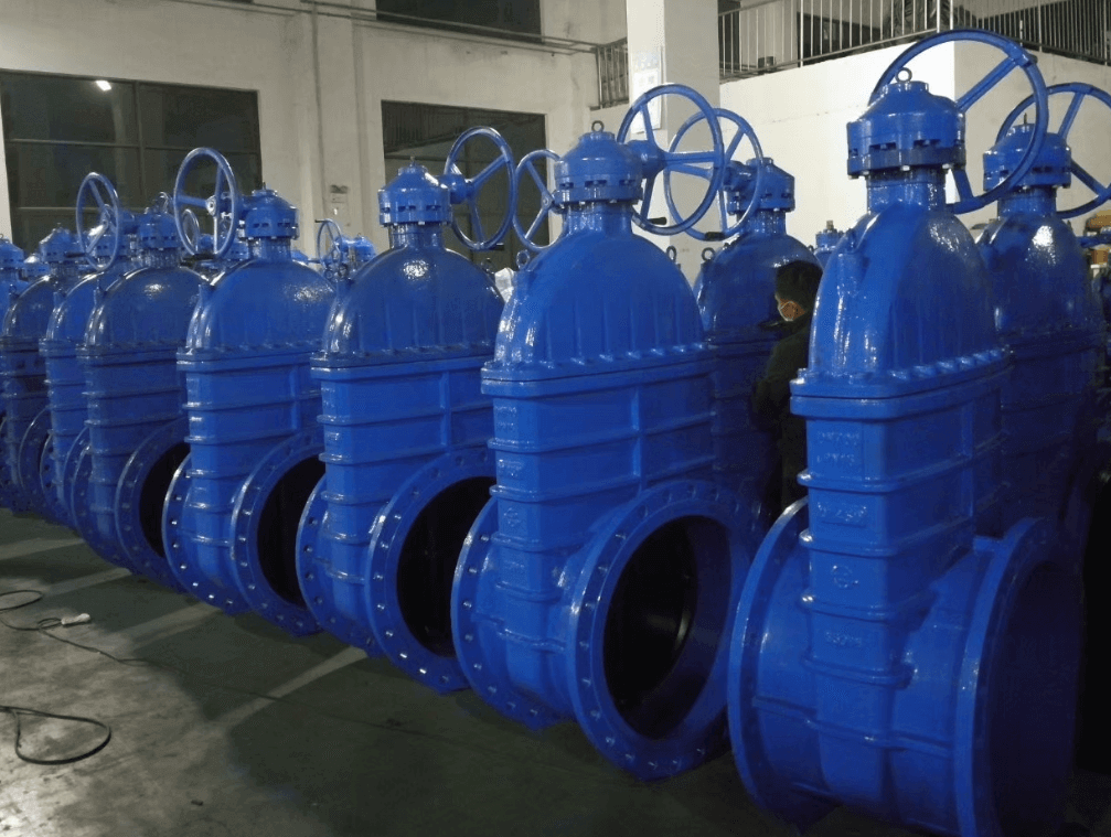
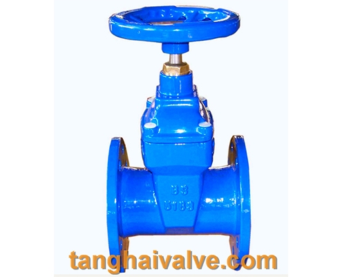
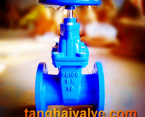
ductile iron soft seal gate valve-non rising stem

ductile iron soft seal gate valve-non rising stem

Classified by valve stem:
According to the stem type, it can be divided into rising-stem gate valve and non rising-stem gate valve. The valve stem is the operating part of the gate valve, and its function is to transmit the opening and closing force to the opening and closing parts.
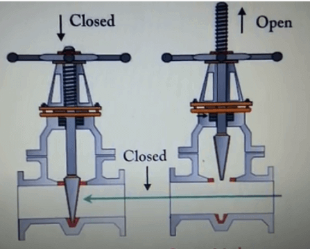
1. The trapezoidal thread of the rising-stem gate valve is placed outside the valve body and located on the upper part of the valve stem. By rotating the valve stem nut, the valve stem drives the disc to rise and fall synchronously to realize the opening and closing of the valve, so it is easy to identify the valve The opening and closing state of the machine can avoid misoperation. Since the stem nut is outside the body cavity, it is beneficial to lubrication, and the opening and closing state is intuitive and obvious, so it is widely used. However, in harsh environments, the exposed threads of the valve stem are vulnerable to damage and corrosion, even affecting operation. Its disadvantage is that the height of the valve after opening is large, usually a stroke is added to the original height of the valve, which requires a lot of operating space.
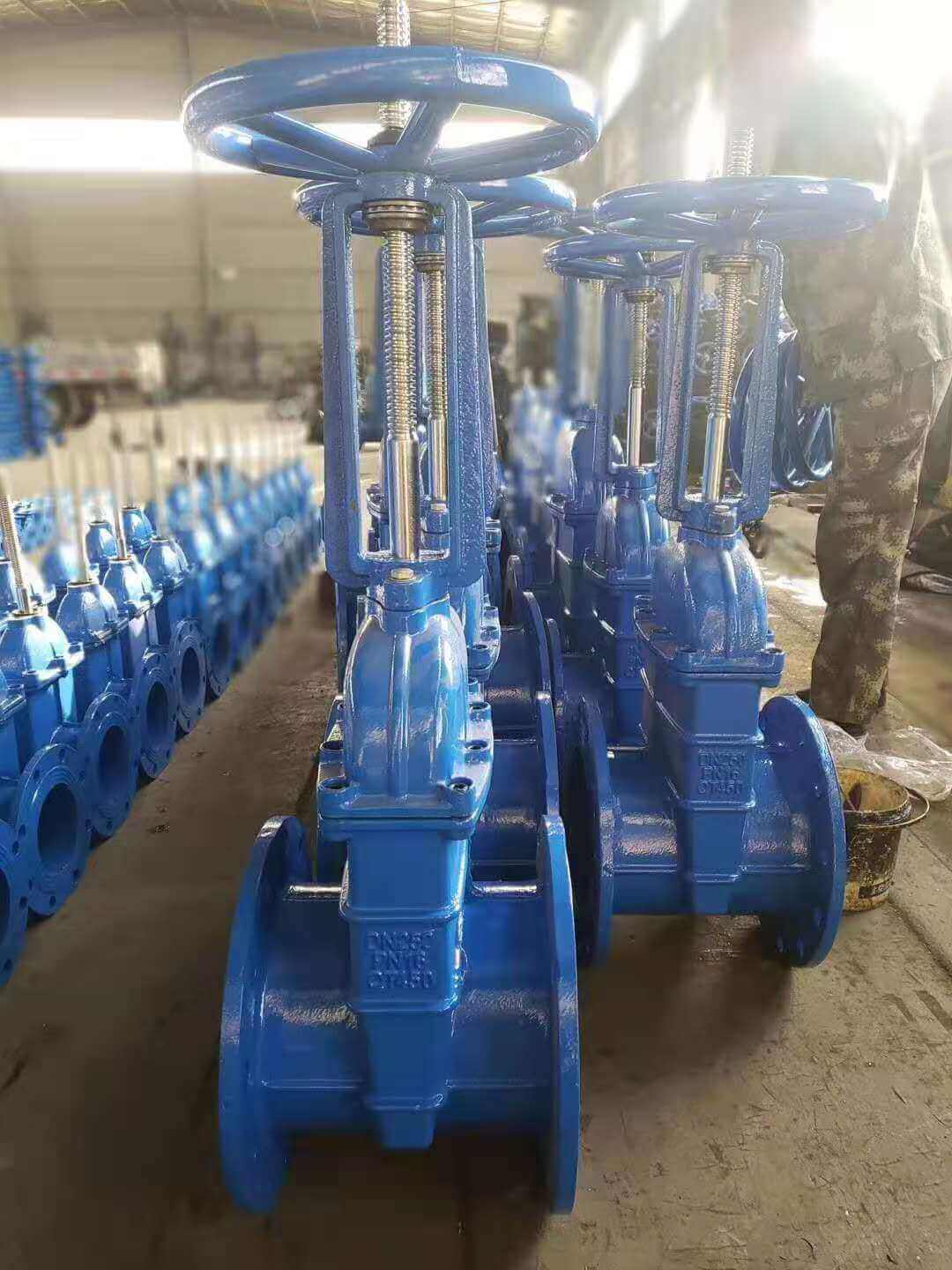
rising stem gate valve-OS&Y (3)

rising stem gate valve-OS&Y (3)

2. Non rising-stem gate valve is also called rotating stem gate valve (also called non rising-stem wedge gate valve). The stem nut is placed inside the valve body and is in direct contact with the medium and is often fixed on the disc. Through the rotation of the valve stem, the valve stem nut drives the disc to move up and down to complete the opening and closing. Usually there is a trapezoidal thread at the bottom end of the valve stem. Through the thread at the bottom end of the valve and the guide groove on the valve disc, the rotary motion is changed into linear motion, that is, the operating torque is turned into operating thrust. Since the trapezoidal thread for transmission is located inside the valve body, it is easily corroded by the medium and cannot be lubricated. The opening degree cannot be directly observed, and an indicating device is required. However, its valve stem does not move up and down, and requires small operating space, so it is suitable for occasions with limited locations and dense pipelines.

Classified by structure:
According to the structure type, it can be divided into two types: wedge gate valve and parallel gate valve. That is, the disc is a wedge type is called a wedge gate valve, and the disc is a parallel type is a flat gate valve.
1. The flat gate valve means that the sealing surface is parallel to the vertical centerline, so the sealing surfaces on the valve body and the disc are also parallel to each other. The most common type of this kind of gate valve is the double disc type. In order to make the valve body and the two sealing surfaces of the disc tightly contacted when it is closed, a double-sided thrust wedge is often used between the two discs. It is mostly used in low pressure pipelines such as small pipelines. Parallel gate valves using a single disc are also available but rare.
2. Wedge gate valve means that the sealing surface is at a certain angle with the vertical center line, that is, the two sealing surfaces are wedge-shaped gate valves. The disc of wedge gate valve is single and double. The advantage of the double disc type is that the accuracy of the sealing angle is lower, the temperature change is not easy to make the disc wedged, and the sealing surface wear can be compensated with gaskets. The disadvantage is that the structure is complex, and it is easy to stick in dry media, and the main reason is that the disc is easy to fall off after the upper and lower baffles are rusted for many years.
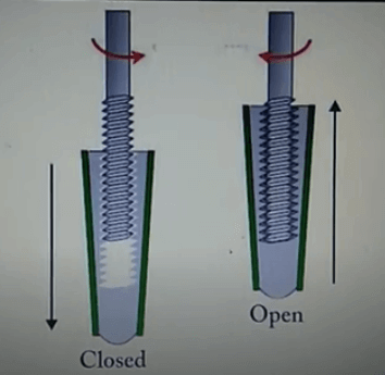
non-rising stem gate valve-open and close position
non-rising stem gate valve-open and close position

rising stem gate valve-open and closed position

rising stem gate valve-open and closed position

Classification by other methods:
According to different standards: national standard gate valve, American standard gate valve, German standard gate valve, Japanese standard gate valve
According to the connection method: flange gate valve, welded gate valve, threaded gate valve (divided into internal thread and external thread)
According to pressure level: high pressure gate valve, low (medium) pressure gate valve
According to the driving mode: electric gate valve, pneumatic gate valve, manual gate valve
Classified by material: stainless steel gate valve, forged steel gate valve, cast steel gate valve, carbon steel gate valve, cast iron gate valve, copper gate valve (also divided into bronze gate valve, brass gate valve), ceramic gate valve, plastic gate valve

The main difference:
1. The lifting screw of the concealed rod flange gate valve only rotates and moves up and down. Only a rod is exposed. The screw cap is fixed on the disc. The disc is raised by the rotation of the screw, and there is no visible electric gate valve frame. ; The lifting screw of the rising stem flange gate valve is exposed, and the screw cap is close to the hand wheel and is fixed (not high-pressure gate valve rotation nor axial movement), the disc is improved by rotating the screw, the screw and the disc have only relative rotational movement There is no relative axial displacement, and the appearance is a gate-shaped bracket.
2. The valve stem with dark stem cannot be seen, while the stem with open stem can be seen.
3. The steering wheel and the valve stem are connected and relatively immovable when the dark stem valve is opened and closed. The valve stem rotates at a fixed point to help the valve clack move upward and downward to complete the opening and closing. The rising stem valve is driven by the turnbuckle of the valve stem and the steering wheel to raise or lower the disc.
To put it simply, the rising stem valve is that the disc and the stem move up and down together, and the steering wheel is always at a fixed point.
Is rising-stem gate valve or non rising-stem gate valve used outdoors?
For the valves installed in the outdoor valve wells, according to the experience of Tanghai valves, it is recommended that you use dark stem valves. The use of rising stem valves has the following disadvantages: 1. When the valve is opened and closed, the valve stem has to rise and fall, which takes up a lot of space. If the pipeline is not buried very deep, the valve well will hinder the opening of the valve. When the valve is opened, the valve well cover will not be closed or the valve cannot be fully opened. 2. After the number of switches is increased, the contact surface of the valve stem and the pressure flange will leak more seriously, and the packing should be replaced frequently. 3. If you don’t switch frequently, a part of the valve stem will be exposed to the valve body for a long time. In the humid environment of the valve well, the exposed valve stem is very easy to oxidize and rust. Once it needs to be closed, it will not be closed. Otherwise, grease must be applied frequently. In short, the maintenance workload is large. Dark stem valves do not have these problems, the probability of water leakage is also small, and of course the maintenance workload is also small. for reference only.

The opening and closing part of the rising-stem gate valve (gate valve) is a disc, and the movement direction of the disc is perpendicular to the direction of the fluid. The rising-stem gate valve can only be fully opened and fully closed, and cannot be adjusted or throttled.

Disc has two sealing surfaces. The two sealing surfaces of the most commonly used mode disc valve form a wedge. The wedge angle varies with valve parameters, usually 50, and 2°52′ when the medium temperature is not high. The disc of the wedge gate valve can be made into a whole, called a rigid disc; it can also be made into a disc that can produce slight deformation to improve its manufacturability and make up for the deviation of the sealing surface angle during the processing. This disc is called an elastic disc .

The types of rising-stem gate valve can be divided into wedge disc gate valve and parallel disc gate valve according to the sealing surface configuration. Wedge disc gate valve can be divided into: single disc type, double disc type and elastic disc type; parallel disc Type gate valve can be divided into single disc type and double disc type. According to the thread position of the valve stem, it can be divided into rising-stem gate valve and non rising-stem gate valve.

When the rising-stem gate valve is closed, the sealing surface can only rely on the medium pressure to seal, that is, only rely on the medium pressure to press the sealing surface of the disc to the valve seat on the other side to ensure the sealing of the sealing surface, which is self-sealing. Most gate valves adopt forced sealing, that is, when the valve is closed, the disc must be forced to the valve seat by external force to ensure the tightness of the sealing surface.
The working principle of rising-stem gate valve
Rotate the hand wheel, through the advance and retreat of the thread of the hand wheel and the valve stem, raise or lower the valve plate connected with the valve stem to open and close
The rising-stem gate valve has the following advantages:
The fluid resistance is small, and the sealing surface is less eroded and eroded by the medium.
It is easier to open and close.
The flow direction of the medium is not restricted, does not disturb the flow, and does not reduce the pressure.
The shape is simple, the length of the structure is short, the manufacturing process is good, and the scope of application is wide.
The disadvantages of rising-stem gate valve are as follows:
It is easy to cause erosion and scratches between the sealing surfaces, and maintenance is difficult.
The overall size is large, opening requires a certain amount of space, and the opening and closing time is long.
The structure is more complicated.
The types of gate valves can be divided into wedge disc gate valves and parallel disc gate valves according to the sealing surface configuration. Wedge disc gate valves can be further divided into: single gate, double disc and elastic disc; parallel disc gate valves can be Divided into single disc type and double disc type. According to the thread position of the valve stem, it can be divided into rising-stem gate valve and non rising-stem gate valve.
Installation and maintenance of rising-stem gate valve:
Handwheels, handles and transmission mechanisms are not allowed to be used for lifting, and collisions are strictly prohibited.
The double disc gate valve should be installed vertically (that is, the valve stem is in the vertical position and the handwheel is at the top).
The gate valve with a bypass valve should be opened before opening (to balance the pressure difference between the inlet and outlet and reduce the opening force).
The gate valve with transmission mechanism should be installed according to the product manual.
If the valve is frequently opened and closed, lubricate at least once a month.

Structural characteristics of rising-stem gate valve:
The general gate valves used on the market for a long time generally have water leakage or rust. The company introduces the elastic seat seal gate valve produced by European high-tech rubber and valve manufacturing technology, which overcomes the defects of poor sealing and rust of general gate valves. The sealing gate valve uses the compensation effect of the elastic disc to produce a small amount of elastic deformation to achieve a good sealing effect. The valve has the obvious advantages of light switch, reliable sealing, good elastic memory and service life. It can be widely used as a regulating and intercepting device on the pipelines of tap water, sewage, construction, petroleum, chemical industry, food, medicine, textile, electric power, shipbuilding, metallurgy, energy system, etc.

Features of rising-stem gate valve:
Light weight: The body is made of high-grade ductile iron, which is about 20% to 30% lighter than the traditional gate valve, and is easy to install and maintain.

Flat-bottomed gate seat: The traditional gate valve often deposits in the groove at the bottom of the valve due to foreign objects such as stones, wood, cement, iron filings, and other debris after the pipe is washed with water. The bottom of the elastic seat-sealed gate valve adopts the same flat-bottom design as the water pipe machine, which is not easy to cause debris siltation and makes the fluid flow unimpeded.

Integral encapsulation: The disc adopts high-quality rubber for the overall inner and outer rubber. European first-class rubber vulcanization technology enables the vulcanized disc to ensure accurate geometric dimensions, and the rubber and ductile disc are connected firmly, not easy to fall off, and have good elastic memory . water

Precision casting valve body: The valve body adopts precision casting, and the precise geometric dimensions make the inside of the valve body without any finishing to ensure the sealing of the valve.
Features of dark-rod soft-seal gate valve:
The overall valve encapsulation is used to produce a deformation compensation effect to achieve a good sealing effect, overcome the poor sealing, water leakage and rust of the general gate valve, and save installation space more effectively. It can be widely used in tap water, sewage, construction, petroleum, chemical, It is used as a regulating and intercepting device on fluid pipelines such as food, medicine, textile, electric power, shipbuilding, metallurgy, energy systems. Our factory introduces European high-tech valve manufacturing technology to produce elastic seat-sealed gate valves, which are deformed by the overall encapsulation of the gate. The compensation effect achieves a good sealing effect and overcomes the phenomenon of poor sealing, water leakage and rust of general gate valves. It can be widely used as a regulating and intercepting device on fluid pipelines such as tap water, sewage, construction, petroleum, chemical industry, food, medicine, minor injuries, electric power, ships, metallurgy, and energy systems.
1. The gate adopts integral rubber encapsulation, and its good covering performance and precise geometric dimensions ensure reliable sealing and longevity.
2. Light weight: The valve body is made of ductile iron, which is light in weight and easy to install.
3. Flat-bottomed valve seat: The bottom is designed with the same flat-bottomed valve seat as the water pipe, which does not produce debris and makes the seal more reliable.
4. Corrosion resistance: The inner cavity is coated with non-toxic epoxy resin to prevent corrosion and rust. Not only can it be used for raw drinking, but also can be used in sewage systems.
5. Three “0” seal: The valve stem is sealed with three O-rings, with low friction resistance, light switch and no water leakage.
How to select the non rising-stem gate valve and rising-stem gate valve?
For oil and natural gas pipelines, single disc or double disc gate valves are used. If you need to clean the pipeline, use a single disc or double disc rising-stem gate valve with diversion holes.
For the transportation pipeline and storage equipment of refined oil, select single disc or double disc gate valve without diversion hole.
For oil and natural gas mining wellhead devices, single disc or double disc gate valves with dark rod floating valve seats and diversion holes are selected, most of which are API16A standards, and the pressure levels are API2000, API3000, API5000, API10000, API15000, API20000.
For pipelines with suspended particulate media, use knife-shaped plate gate valves.
The city gas transmission pipeline adopts single disc or double disc soft-sealed rising-stem gate valve.
For urban tap water projects, single disc or double disc rising-stem gate valve without diversion hole is used.

The role and classification of valves

Valves have many functions. Different valves should be selected for different functions. Different types of valves have

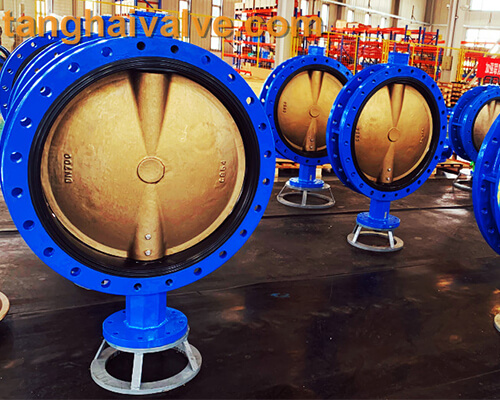
U-type-flange-butterfly-valve-2

U-type-flange-butterfly-valve-2

different structures. These functions are all means to effectively control the process and ensure safety. Valves are generally divided into automatic valves and drive valves. Automatic valves (such as safety valves, pressure reducing valves, steam traps, check valves) rely on changes in the pressure of the device or pipeline to achieve the purpose of opening and closing. Driving valves (gate valves, globe valves, ball valves, butterfly valves, etc.) rely on driving devices (manual, electric, hydraulic, pneumatic, etc.) to adjust the pressure, flow and direction of the medium in the pipeline. Due to the different pressure, temperature, flow rate and physical and chemical properties of the medium, the control requirements and use requirements of the device and piping system are also different, so the role of the valve is also different.
Classified by valve function:
Cut-off valve: The cut-off valve is also called a closed-circuit valve. Its function is to connect or cut off the medium in the pipeline. Block valves include gate valves, globe valves, plug valves, ball valves, butterfly valves and diaphragm

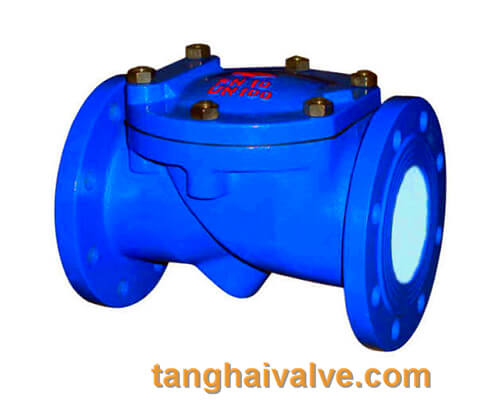
8 tilting-disc-swing-check-valve-3

8 tilting-disc-swing-check-valve-3

valves.
Regulating valve: Regulating valves include regulating valves, throttle valves and pressure reducing valves, whose function is to regulate the pressure and flow of the medium.
Check valve: Check valve is also called one-way valve or check valve, its function is to prevent the medium in the pipeline from flowing back. The bottom valve of the pump to close the water is also a check valve.
Safety valve: The function of safety valves is to prevent the pressure of the medium in the pipeline or device from exceeding the specified value, so as to achieve the purpose of safety protection.
Diversion valve: Diversion valves include various distribution valves and traps, etc., whose function is to distribute, separate or mix the medium in the pipeline.
Exhaust valve: Exhaust valve is an indispensable auxiliary component in the pipeline system. It is often installed at high points or elbows to remove excess gas in the pipeline, improve the efficiency of pipeline use and reduce energy consumption.
The role of the valve: (cut-off, adjustment, check, safety)
1. Cut-off function An important function of the valve is the cut-off function. It is to cut off (shut off) the fluid in the pipeline to prevent it from circulating. Generally, the valves of various pipelines mainly play a cut-off role. To
2. Regulation function Another important function of the valve is to adjust the flow rate. According to the working conditions or use requirements, adjust the media flow, temperature, pressure, liquid level and other parameters in the pipeline. The control of this flow depends on the valve opening. To adjust the size of the degree. [Electric regulating ball valve Electric regulating butterfly valve Pneumatic regulating ball valve Pneumatic regulating butterfly valve]
3. Non-reverse function Some pipelines require the medium to flow in one direction, and no reverse flow or backflow is allowed. This requires the use of non-reverse valves (or one-way valves). It refers to a valve that automatically opens and closes the valve flaps depending on the flow of the medium itself to prevent the medium from flowing back. It is an automatic valve. Its main function is to prevent the medium from flowing back, prevent the pump and drive motor from reversing, and the container medium. put.
4. Safety function In order to prevent explosion accidents when the fluid pressure in the high-pressure container exceeds the pressure limit of the container when the pressure is too high, a valve that can automatically release pressure at a certain pressure is installed on the container, which is generally called a safety valve. For example, boilers, compressed air storage tanks and some high-pressure reactors are equipped with safety valves. This valve plays a role in ensuring safety.
5. Other functions In addition to the above four functions, the valve also has some functions, such as stabilizing the pressure of the system; reducing the high pressure in front of the valve to a lower pressure reducing effect, and releasing the pressure by venting to discharge sewage The function of sewage discharge; the sampling function of sampling for analysis and observation; and the backflow function of returning part of the fluid to the previous process. There are also steering valves (three-way valve, four-way valve, etc.) that transfer fluid to another pipeline.

TH Valve is a professional manufacturer of butterfly valvegate valvecheck valveglobe valveknife gate valve, ball valve with API, JIS, DIN standard, used in Oil, Gas, Marine industry, Water supply and drainage, fire fighting, shipbuilding, water treatment and other systems, with Nominal Diameter of DN50 to DN1200, NBR/EPDM/VITON, Certificates & Approvals: DNV-GL, Lloyds, DNV, BV, API, ABS, CCS. Standards: EN 593, API609, API6D

related news /knowledge: The difference between globe valve and check valve; The matching function and principle of pneumatic valve accessories; 

Valve selection basis and selection guide

How to select the righty type of valve? the following article will give you an idea how to choose the right structure/type valve.

Nowadays, there are more and more valves on the market, the types of valves are particularly complex, and the

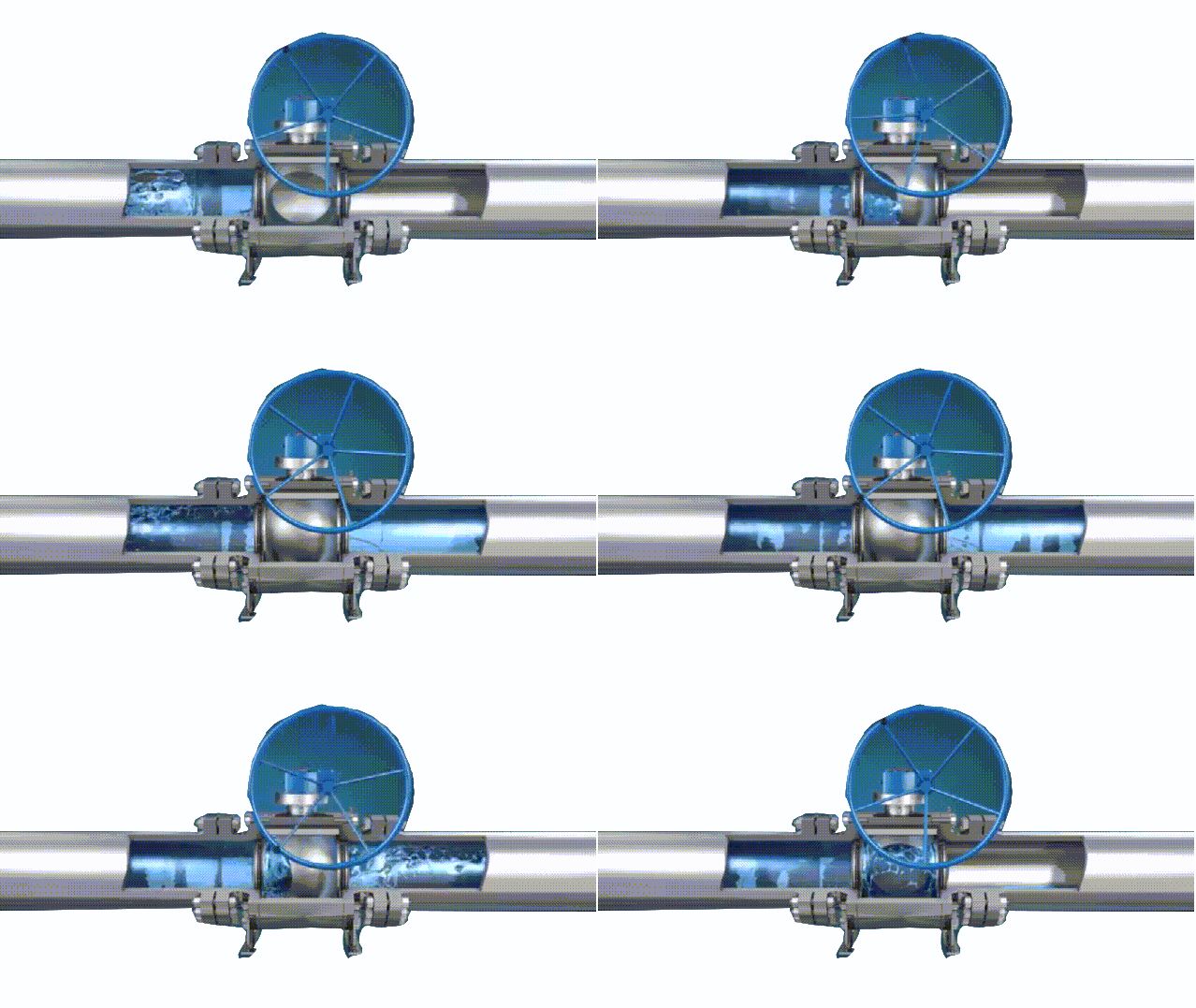
ball valve working diagram-3D GIF animated presentation

ball valve working diagram-3D GIF animated presentation

structures and materials are all different. The selection of valves is very important for the long-term operation of the device in working conditions. Improper selection of valves and users’ ignorance of valves are the source of accidents and safety threats. Nowadays, the demand for valve products in the social industry is becoming more and more extensive, and users should have a further understanding and cognition of knowledge about valves and other aspects.

There are generally two types of valve characteristics, use characteristics and structural characteristics.

Use characteristics of the valve: It determines the main use performance and use range of the valve. The

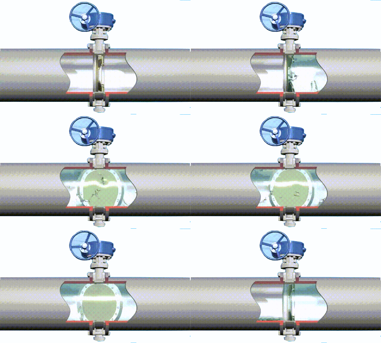
butterfly valve working diagram-3D GIF animated presentation

butterfly valve working diagram-3D GIF animated presentation

characteristics of the valve use include: valve category (closed circuit valve, regulating valve, safety valve, etc.); product type (gate valve, globe valve, butterfly valve, ball valve) Etc.); the materials of the main parts of the valve (valve body, bonnet, valve stem, valve disc, sealing surface); valve transmission mode, etc.

The structural characteristics of the valve: it determines the structural characteristics of the valve installation, repair, maintenance and other methods. The structural characteristics include: the structural length and overall height of the valve, the connection form with the pipeline (flange connection, threaded connection, clamp Connection, external thread connection, welding end connection, etc.); the form of the sealing surface (inlaid ring, threaded ring, surfacing, spray welding, valve body); valve stem structure (rotating rod, lifting

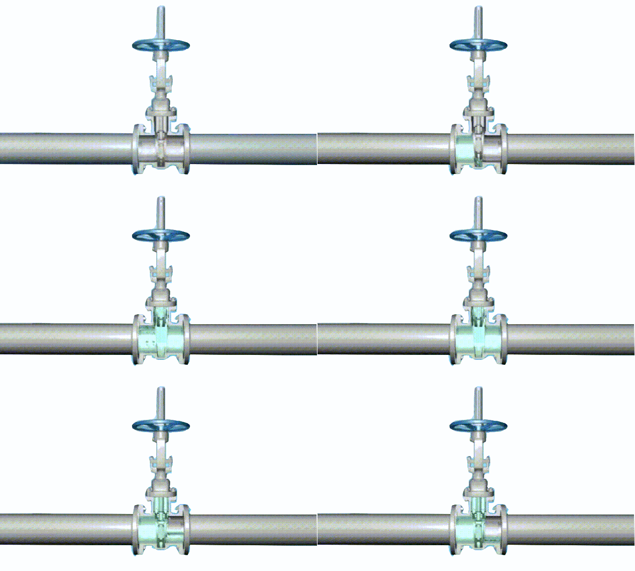
gate valve working diagram-3D GIF animated presentation

gate valve working diagram-3D GIF animated presentation

rod), etc.

Valve selection steps:
1. Clarify the purpose of the valve in the equipment or device, and determine the working conditions of the valve: applicable medium, working pressure, working temperature, etc.
2. Determine the nominal diameter and connection method of the pipe connected to the valve: flange, thread, welding, ferrule, quick installation, etc.
3. Determine the method of operating the valve: manual, electric, electromagnetic, pneumatic or hydraulic, electrical linkage or electrohydraulic linkage, etc.
4. Determine the material of the valve housing and internal parts according to the medium, working pressure and

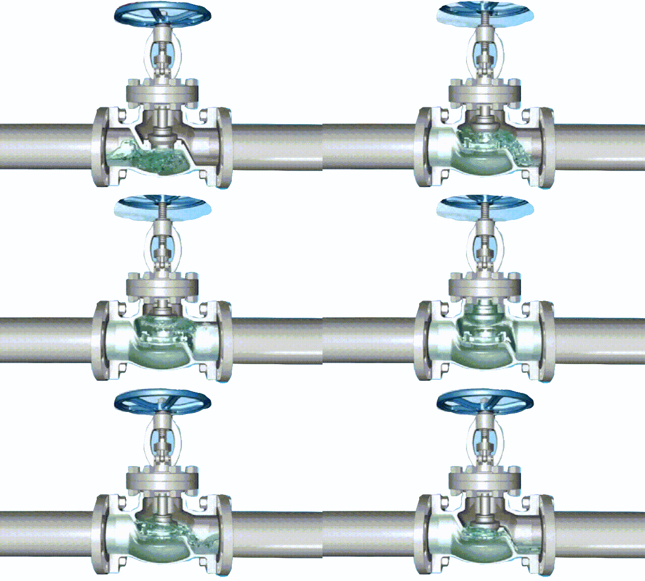
globe cut-off valve working diagram-3D GIF animated presentation

globe cut-off valve working diagram-3D GIF animated presentation

working temperature conveyed by the pipeline: gray cast iron, malleable cast iron, ductile iron, carbon steel, alloy steel, stainless acid-resistant steel, copper alloy, etc.
5 Select the type of valve: closed circuit valve, regulating valve, safety valve, etc.
6. Determine the valve type: gate valve, globe valve, ball valve, butterfly valve, throttle valve, safety valve, pressure reducing valve, steam trap, etc.
7. Determine the parameters of the valve: For automatic valves, first determine the allowable flow resistance, discharge capacity, back pressure, etc., according to different needs, and then determine the nominal diameter of the pipeline and the diameter of the valve seat hole.
8. Determine the geometric parameters of the selected valve: structural length, flange connection form and size, valve height dimension after opening and closing, connecting bolt hole size and number, overall valve outline size,

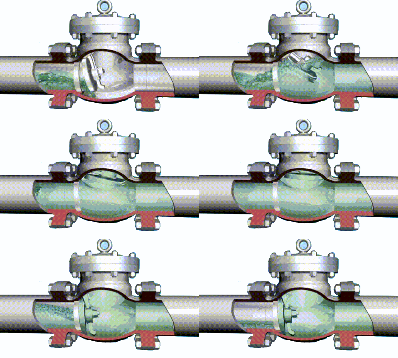
tilting disc swing check valve working diagram-3D GIF animated presentation

tilting disc swing check valve working diagram-3D GIF animated presentation

etc.
9. Use existing information: valve product catalog, valve product sample, etc. to select appropriate valve products.

Basis for valve selection:
1. The purpose, operating conditions and operation control mode of the selected valve.
2. The nature of the working medium: working pressure, working temperature, corrosion performance, whether it contains solid particles, whether the medium is toxic, whether it is flammable or explosive medium, the viscosity of the medium, etc.
3. Requirements for valve fluid characteristics: flow resistance, discharge capacity, flow characteristics, sealing level, etc.
4. Requirements for installation dimensions and external dimensions: nominal diameter, connection to the pipeline and connection dimensions, external dimensions or weight restrictions, etc.
5. Additional requirements for the reliability and service life of valve products and the explosion-proof performance of electric devices. (Note when selecting parameters: If the valve is to be used for control purposes, the following additional parameters must be determined: operation method, maximum and minimum flow requirements, pressure drop for normal flow, pressure drop when closed, maximum and minimum inlets of the valve Pressure.)

According to the above-mentioned basis and steps for selecting valves, the internal structure of various types of valves must be understood in detail when selecting valves reasonably and correctly, so that the correct choice can be made on the preferred valve. The ultimate control of the pipeline is the valve. The valve opening and closing parts control the flow mode of the medium in the pipeline. The shape of the valve flow channel makes the valve have a certain flow characteristic. This must be considered when selecting the most suitable valve for the pipeline system.

Types and selection of electric valves

Types of electric valves:
Electric valves are valves driven by electric energy, mainly composed of electric actuators and various types of valves.

double eccentric butterfly valve (2)

double eccentric butterfly valve (2)

Because the electric valve is easy to use and can be operated when the power is turned on, it is the longest-used type of automatic control valve. There are many types of electric valves. Commonly used are electric control valves, electric ball valves, electric butterfly valves, electric gate valves, and electric globe valves. Different types of electric valves have different applications.

1. The electric control valve can choose different valve structures and spool types according to the working conditions of the medium. It is mainly suitable for high, medium and low pressure pipelines with various media to adjust pipeline parameters. With the increasing requirements in the field of modern industrial automation, electric control valves are becoming more and more widely used. Different materials can be used to use various liquid and gas media pipelines.

2. Electric ball valve and electric butterfly valve are the most widely used electric valve models, equipped with different actuators, which can not only realize the two-position cut-off of the pipeline, but also can be used for occasions where the linearity requirements are not too strict. Electric butterfly valves There are two connection methods: wafer type and flange type. Normal pressure and large diameter pipes are mostly used. Electric ball valves and electric butterfly valves are similar in use, but they use more pressure than electric butterfly valves.

3. Both the electric gate valve and the electric shut-off valve have a blocking function in the pipeline, but it should be noted that these two types of valves cannot be used for adjustment. It is suitable for all kinds of large diameter, high, medium and low pressure medium working conditions.

Electric valve selection:
Electric valves are usually valves that are driven by a motor. Because the motor needs to be decelerated to drive the valve to open and close, it is generally not recommended to use electric if it is required to close and open the valve quickly. Basically, you can choose electromagnetic quick-closing valve, pneumatic or hydraulic quick-closing valve. Close the valve. But if necessary, you must choose an electric type of quick-closing valve, then you should choose an electric butterfly valve or an electric ball valve, because this type of valve has a short switching stroke.

Classification of valves

Valve classification by function and purpose:

ductile iron, DI, butterfly valve, manufacturer, center line, TH valve

ductile iron, DI, butterfly valve, manufacturer, center line, TH valve

(1) Cut-off type: such as gate valve, globe valve, plug valve, ball valve, butterfly valve, needle valve, diaphragm valve, etc. The cut-off valve is also called a closed-circuit valve or a cut-off valve, whose function is to connect or cut off the medium in the pipeline.

Check valve, also known as one-way valve or check valve, check valve is an automatic valve, its function is to prevent the back flow of the medium in the pipeline, prevent the pump and drive motor from reversing, and the leakage of the container medium . The bottom valve of the pump to close the water is also a check valve.

Explosion-proof valves, emergency valves, etc. The role of safety valves is to prevent the pressure of the medium in the pipeline or device from exceeding the specified value, so as to achieve the purpose of safety protection.

Regulating valve, throttle valve and pressure reducing valve, its role is to adjust the pressure, flow and other parameters of the medium.

(2) Vacuum: such as vacuum ball valve, vacuum baffle valve, vacuum charging valve, pneumatic vacuum valve, etc. Its role is in the vacuum system to change

The vacuum system components that adjust the air flow direction, cut off or connect the pipeline are called vacuum valves.

(3) Special purpose categories: such as pigging valve, vent valve, drain valve, exhaust valve, filter, etc. The exhaust valve is an indispensable auxiliary component in the pipeline system, which is widely used in boilers, air conditioners, oil and gas, and water supply and drainage pipelines. It is often installed at high points or elbows to remove excess gas in the pipeline, improve the efficiency of pipeline use and reduce energy consumption.

According to the main parameters:

According to the nominal pressure:

lug type butterfly valve, ductile iron, center lined,

lug type butterfly valve, ductile iron, center lined,

  • (1) Vacuum valve: refers to a valve whose working pressure is lower than the standard atmospheric pressure.
  • (2) Low pressure valve: refers to the valve with a nominal pressure PN ≤ 1.6Mpa.
  • (3) Medium pressure valve: refers to valves with nominal pressure PN of 2.5Mpa, 4.0Mpa, 6.4Mpa.
  • (4) High-pressure valve: refers to the valve whose nominal pressure PN is 10.0Mpa~80.0Mpa.
  • (5) Ultra-high pressure valve: refers to a valve with a nominal pressure PN≥100.0Mpa.
  • (6) Filter: Refers to the nominal pressure PN is 1.0Mpa, 1.6Mpa

According to working temperature

  • (1) Ultra-low temperature valve: used for valves with medium working temperature t<-101℃.
  • (2) Normal temperature valve: used for valves with medium working temperature -29℃<t<120℃.
  • (3) Medium temperature valve: used for valves with a working temperature of 120℃<t<425℃.
  • (4) High temperature valve: used for valves with medium working temperature t>425℃.

By driving method:

According to the driving mode, it is divided into automatic valves, power-driven valves and manual valves

Valves driven by compressed air. Hydraulic valve: A valve driven by the pressure of liquids such as oil.

In addition, there are combinations of the above several driving methods, such as pneumatic-electric valves.

According to the nominal diameter:

  • (1) Small diameter valve: Valve with nominal diameter DN≤40mm.
  • (2) Middle diameter valve: a valve whose nominal diameter DN is 50~300mm.
  • (3) Large diameter valve: a valve with a nominal valve DN of 350~1200mm.
  • (4) Extra large diameter valves: valves with nominal diameter DN ≥ 1400mm

6. According to structural characteristics:

Valve structure characteristics:

The structural features of the valve can be divided into:

  • (1) Sectional gate shape: The closing part moves along the center of the valve seat; such as a globe valve
  • (2) Cock and ball: The closing part is a plunger or a ball, which rotates around its own centerline; such as a plug valve, a ball valve
  • (3) Gate shape: The closing part moves along the center of the vertical valve seat; such as gate valve, gate, etc.
  • (4) Swing shape: The closing part rotates around the axis outside the valve seat; such as swing check valve, etc.
  • (5) Butterfly shape: the disc of the closing part, which rotates around the axis in the valve seat; such as butterfly valve, butterfly check valve, etc.
  • (6) Slide valve shape: The closing piece slides in a direction perpendicular to the channel. Slippery

Press connection method:

  • (1) Threaded connection valve: The valve body has an internal thread or an external thread, which is connected with the pipe thread…
  • (2) Flange connection valve: The valve body has a flange and is connected to the pipeline flange.
  • (3) Welding connection valve: The valve body has a welding groove and is welded to the pipeline.
  • (4) Clamp connection valve: The valve body has a clamp, which is connected with the pipe clamp.
  • (5) Ferrule connection valve: the ferrule is connected to the pipeline.
  • (6) Wafer connection valve: a connection form in which the valve and two pipes are directly clamped together with bolts.

According to the body material

  • (1) Metal material valve: its valve body and other parts are made of metal material. Such as cast iron valves, cast steel valves, alloy steel valves, copper alloy valves, aluminum alloy valves, lead alloy valves, titanium alloy valves, Monel alloy valves, etc.
  • (2) Non-metallic material valve: its valve body and other parts are made of non-metallic material. Such as plastic valves, enamel valves, ceramic valves, FRP valves, etc.

TH Valve is a professional manufacturer of butterfly valvegate valvecheck valveglobe valveknife gate valve, ball valve with API, JIS, DIN standard, used in Oil, Gas, Marine industry, Water supply and drainage, fire fighting, shipbuilding, water treatment and other systems, with Nominal Diameter of DN50 to DN1200, NBR/EPDM/VITON, Certificates & Approvals: DNV-GL, Lloyds, DNV, BV, API, ABS, CCS. Standards: EN 593, API609, API6D

Related news/knowledge:
Notes on selection and installation of butterfly valve;
Classification of check valves;
Classification and advantages of gate valve;
The main classification methods of butterfly valve (1)

Knife gate valve introduction and its characteristics

Knife gate valve entered China in the 1980s. In less than two decades, its use has expanded from ordinary fields to a

Knife gate valve (1)

Knife gate valve (1)

wider range of industries, from coal preparation, gangue discharge, and slag discharge in mines and power plants to Urban sewage treatment has evolved from general industrial pipelines to specialized pipeline systems for food, sanitation, and medicine.

What is a knife gate valve:
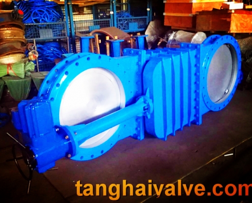
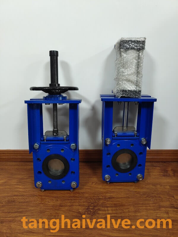
Knife gate valve-also known as knife door valve, knife-type slurry valve, entered my country in the 1980s. In less than two decades, its scope of use has expanded from the general field to a wider range of industries. Coal preparation, gangue discharge and slag discharge from mines and power plants. It has developed into urban sewage treatment, from general industrial pipelines to professional pipeline systems such as food, sanitation, and medicine. The ultra-thin knife gate valve completely solves the large flow resistance of ordinary gate valves, flat gate valves, ball valves, globe valves, regulating valves, butterfly valves and other valves with its advantages of small size, small flow resistance, light weight, easy installation, and easy disassembly. , Heavy weight, difficult installation, large area and other difficult problems. After the emergence of knife gate valves, a large number of general shut-off valves and regulating valves have been replaced. To date, the world’s largest consumption of knife gate valves is the United States and Japan.

Characteristics of knife gate valve:

Knife gate valve-

Knife gate valve-

1. Valve control can be used for local and remote control, and can also realize remote position display and remote centralized control according to user requirements.

2. Light weight: The body is made of carbon steel, and the weight is about 20%-30% lighter than the traditional gate valve. It is easy to install and maintain.

3. The use of this valve can improve the closing and sealing performance of the conveying pipeline system, prevent leakage to the maximum extent, and play a positive role in improving production efficiency and protecting the environment.

4. The sealing surface is made of highly wear-resistant and corrosion-resistant ceramic materials, and the use of inlay technology has high corrosion resistance and good wear resistance, so that the valve has a long life and the cost performance is 10 times higher than that of ordinary valves.

TH Valve is a professional manufacturer of butterfly valvegate valvecheck valveglobe valveknife gate valve, ball valve with API, JIS, DIN standard, used in Oil, Gas, Marine industry, Water supply and drainage, fire fighting, shipbuilding, water treatment and other systems, with Nominal Diameter of DN50 to DN1200, NBR/EPDM/VITON, Certificates & Approvals: DNV-GL, Lloyds, DNV, BV, API, ABS, CCS. Standards: EN 593, API609, API6D

Related news/knowledge:
Pneumatic gate valve model preparation method;
Gate valve model meaning and representation method;
Gate valve structure diagram and working principle;

Gate valve characteristics and installation notes

Gate valve characteristics:
Light weight
The body is made of high-grade nodular cast iron, the weight is about 20%~30% less than the weight of traditional

13 gate-valve-5

13 gate-valve-5

gate valve, and the installation and maintenance are convenient.

Flat bottom brake seat:
Traditional gate valves often silt in the grooves at the bottom of the valve due to foreign objects such as stones, wood, cement, iron filings, sundries, etc., after the pipe is washed with water, which can easily cause water leakage. The bottom of the gate valve is sealed by elastic seating. It adopts the same flat-bottom design as the water pipe machine, which is not easy to cause debris accumulation and makes the fluid flow unimpeded.

Overall encapsulation:
The gate adopts high-quality rubber for the overall inner and outer rubber. European rubber vulcanization technology enables the vulcanized gate to ensure accurate geometric dimensions, and the rubber and ductile cast gate are firmly connected, not easy to fall off and have good elastic memory.

Precision casting valve body:
The valve body is made of precision casting, and the precise geometric dimensions make the inside of the valve body without any finishing to ensure the sealing of the valve.

Installation Precautions of gate valve:
1. Handwheels, handles and transmission mechanisms are not allowed to be used for lifting, and collisions are strictly prohibited.

2. The double gate valve should be installed vertically (that is, the valve stem is in the vertical position and the handwheel is on the top).

3. The gate valve with a bypass valve should be opened before opening (to balance the pressure difference between the inlet and outlet and reduce the opening force).

4. The gate valve with transmission mechanism should be installed according to the product manual.

5. If the valve is frequently opened and closed, lubricate at least once a month.

6. The gate valve is only used for the operation of the medium on various pipelines or equipment, which is fully open and fully closed, and is not allowed to be used for throttling.

7. For gate valves with hand wheels or handles, no auxiliary levers should be added during operation (if the sealing is not tight, the sealing surface or other parts should be checked and repaired). Turn the handwheel and handle clockwise to close, otherwise open. The gate valve with transmission mechanism should be used in accordance with the product manual.

Installation points of gate valve:

1) The installation position, height, and direction of inlet and outlet must meet the design requirements, and the connection should be firm and tight.

2) All kinds of manual valves installed on the thermal insulation pipeline must not handle downwards.

3) Visual inspection must be carried out before the valve is installed. The nameplate of the valve should comply with the current national standard “General Valve Marking” GB 12220. For valves with a working pressure greater than 1.0 MPa and a cut-off function on the main pipe, the strength and tightness performance test should be carried out before installation, and the valve can be used only after it is qualified. During the strength test, the test pressure is 1.5 times the nominal pressure, and the duration is not less than 5 min. The valve housing and packing should be qualified without leakage. During the tightness test, the test pressure is 1.1 times the nominal pressure; the test pressure should meet the requirements of the GB 50243 standard during the test duration, and no leakage on the valve flap sealing surface is qualified.

4) The hand wheel, handle and transmission mechanism are not allowed to be used for lifting, and collision is strictly prohibited.

5) The gate valve with transmission mechanism should be installed according to the product manual.

TH Valve is a professional manufacturer of butterfly valvegate valvecheck valveglobe valveknife gate valve, ball valve with API, JIS, DIN standard, used in Oil, Gas, Marine industry, Water supply and drainage, fire fighting, shipbuilding, water treatment and other systems, with Nominal Diameter of DN50 to DN1200, NBR/EPDM/VITON, Certificates & Approvals: DNV-GL, Lloyds, DNV, BV, API, ABS, CCS. Standards: EN 593, API609, API6D

Related news /products:
Stainless steel valve material parameters and specific applications;
Common failures of butterfly valves and the characteristics of installation;
Uses and characteristics of manual butterfly valve (4);
Hard seal installation method of ball valve

Classification and advantages of gate valve

Gate valve types:

There are many domestic manufacturers of gate valves, and most of the connection dimensions are not uniform.

gate valve (3)

gate valve (3)

Mainly divided into the following categories: 1. According to JB/T2203-1999 “Structural Length of Gate Valve”, the standard valve of the Ministry of Machinery; 2. According to GB/T12221-2005 “Metal Valve Structure Length”, the national standard valve; 3. According to American standard valves produced by ASME B16.10-2009 “Face-to-face and End-to-End Dimensions of Valves”.

Gate valves are divided into wedge type and parallel type according to the structure of the gate. There are 3 types of wedge gates: single gate, double gate and elastic gate.

Gate valves are divided into flat gate valves and knife gate valves according to their structure types.

The working principle of manual gate valve: Turn the hand wheel, and the valve plate connected with the valve stem can be lifted or lowered by the thread of the hand wheel and the valve stem to open and close.

According to the classification of shell/body material, gate valves can be divided into:

Metal material valves: such as carbon steel valves, alloy steel valves, stainless steel valves, cast iron valves, titanium alloy valves, Monel valves, copper alloy valves, lead alloy valves, etc.

Metal valve body lining valves: such as rubber-lined valves, fluorine-lined valves, lead-lined valves, plastic-lined valves, and enamel-lined valves.

Non-metallic materials valves: such as ceramic valves, glass valves, plastic valves.

Advantages of gate valve:
1. Small flow resistance. The medium channel inside the valve body is straight, the medium flows in a straight line, and the flow resistance is small.
2. Less effort when opening and closing. It is compared with the shut-off valve, because whether it is open or closed, the direction of movement of the gate is perpendicular to the direction of medium flow.
3. Large height and long opening and closing time. The opening and closing stroke of the gate is large, and the lifting is carried out by the screw.
4. Water hammer is not easy to produce. The reason is the long closing time.
5. The medium can flow in any direction on both sides, easy to install. Both sides of the gate valve channel are symmetrical.
6. The structural length (the distance between the two connecting end faces of the shell) is small.
7. Simple shape, short structure length, good manufacturing technology and wide application range.
8. Compact structure, good valve rigidity, smooth passage, small flow resistance, stainless steel and hard alloy sealing surface, long service life, PTFE packing, reliable sealing, light and flexible operation.

Disadvantages of gate valve:

It is easy to cause erosion and scratches between the sealing surfaces, and maintenance is difficult. The overall size is large, opening requires a certain amount of space, and the opening and closing time is long. The structure is more complicated.

Working principle and movement mode of gate valve

The gate valve is a gate for opening and closing. The movement direction of the gate is perpendicular to the direction

13 gate-valve-5

13 gate-valve-5

of the fluid. The gate valve can only be fully opened and fully closed, and cannot be adjusted or throttled. The gate valve is sealed through the contact between the valve seat and the gate plate. Usually, the sealing surface will be welded with metal materials to increase wear resistance, such as 1Cr13, STL6, stainless steel, etc. The gate has a rigid gate and an elastic gate. According to the difference of the gate, the gate valve is divided into a rigid gate valve and an elastic gate valve.

Working principle of gate valve:
The opening and closing part of the gate valve is a gate. The movement direction of the gate is perpendicular to the direction of the fluid. The gate valve can only be fully opened and fully closed, and cannot be adjusted or throttled. The gate has two sealing surfaces. The two sealing surfaces of the most commonly used model gate valve form a wedge. The wedge angle varies with valve parameters, usually 5°, and 2°52′ when the medium temperature is not high. The gate of the wedge gate valve can be made into a whole, called a rigid gate; it can also be made into a gate that can produce slight deformation to improve its manufacturability and compensate for the deviation of the sealing surface angle during the processing. The plate is called an elastic gate. When the gate valve is closed, the sealing surface can only rely on the medium pressure to seal, that is, relying on the medium pressure to press the sealing surface of the gate to the valve seat on the other side to ensure the sealing of the sealing surface, which is self-sealing. Most gate valves adopt forced sealing, that is, when the valve is closed, the gate must be forced against the seat by external force to ensure the sealing performance of the sealing surface. The gate valve of the gate valve moves linearly with the valve stem, which is called the lifting stem gate valve, also called the rising stem gate valve. Usually there is a trapezoidal thread on the lifting rod, through the nut on the top of the valve and the guide groove on the valve body, the rotary motion is changed into linear motion, that is, the operating torque is turned into operating thrust. When the valve is opened, when the lift height of the gate is equal to 1:1 times the valve diameter, the fluid channel is completely unblocked, but this position cannot be monitored during operation. In actual use, the apex of the valve stem is used as the mark, that is, the position where it cannot be opened, as its fully open position. In order to take into account the locking phenomenon of temperature changes, it is usually opened to the top position, and then back 1/2-1 circle, as the position of the fully open valve. Therefore, the fully open position of the valve is determined by the position of the gate, that is, the stroke. In some gate valves, the stem nut is set on the gate, and the rotation of the handwheel drives the rotation of the valve stem to lift the gate. This kind of valve is called a rotating stem gate valve, or a dark stem gate valve.

Movement mode of gate valve:
When the gate valve is closed, the sealing surface can only rely on the medium pressure to seal, that is, only rely on the medium pressure to press the sealing surface of the gate to the valve seat on the other side to ensure the sealing of the sealing surface, which is self-sealing. Most gate valves adopt forced sealing, that is, when the valve is closed, the gate must be forced against the seat by external force to ensure the sealing performance of the sealing surface.

Movement mode: The gate of the gate valve moves linearly with the valve stem, which is also called the rising stem gate valve. Usually there is a trapezoidal thread on the lifting rod, through the nut on the top of the valve and the guide groove on the valve body, the rotary motion is changed into linear motion, that is, the operating torque is changed into operating thrust. When the valve is opened, when the lift height of the gate is equal to 1:1 times the valve diameter, the fluid channel is completely unblocked, but this position cannot be monitored during operation. In actual use, the apex of the valve stem is used as the mark, that is, the position where it cannot be opened, as its fully open position. In order to take into account the locking phenomenon due to temperature changes, it is usually opened to the top position, and then rewind 1/2-1 turn, as the position of the fully open valve. Therefore, the fully open position of the valve is determined by the position of the gate (i.e. stroke). Some gate valve stem nuts are set on the gate, and the rotation of the handwheel drives the rotation of the valve stem to lift the gate. This kind of valve is called Rotating stem gate valve or dark stem gate valve.

Difference between Soft seal gate valve and hard seal gate valve

Soft seal gate valve and hard seal gate valve are two major categories in the gate valve series. Hard seal and soft seal can sometimes compensate for each other, and

13 gate-valve-5

13 gate-valve-5

sometimes they are independent of each other. So what is the relationship between soft seal gate valve and hard seal gate valve? What are the main differences? Next, the editor of Tanghai Valve will solve these mysteries for everyone.

1. Sealing material

Soft seal gate valve: the seal pair is made of metal materials on one side and elastic non-metallic materials on the other side, which is called “soft seal”. This kind of seal has good sealing performance, but it is not resistant to high temperature, easy to wear, and has poor mechanical properties.

Hard seal gate valve: The two sides of the seal pair are made of metal materials or other harder materials are called “hard seals”. This kind of seal has poor sealing performance, but has high temperature resistance, abrasion resistance and good mechanical properties.

2. Structure mechanism

The hard seal gate valve is a seal between metal and metal, and the sealing ball and valve seat are both metal. Machining accuracy and craftsmanship are more difficult, and are generally used in high pressure, usually above 35MPa. The soft seal gate valve is a seal between metal and non-metal, such as nylon\tetrafluoroethylene, and the manufacturing standards are the same.

3. Equipment selection

The selection of soft and hard seal gate valves is mainly based on the process medium, temperature and pressure. Generally, the medium contains solid particles or wears or the temperature is higher than 200 degrees. It is best to use hard seals. Valves with a diameter greater than 50 have a larger pressure difference and consider opening the valve torque. , When the torque is large, the fixed hard-seal ball valve should be selected, and its sealing level can reach 6 regardless of the soft or hard seal.

3. Conditions of use

The soft seal gate valve generally has a very high seal, while the hard seal can be high or low according to the requirements; the soft seal needs to be fireproof, because the material of the soft seal will leak at high temperatures, while the hard seal does not have this problem; Seals can generally be made at very high pressures, but soft seals cannot; soft seals cannot be used in some situations due to the problem of the flowing medium. Finally, hard seal valves are generally more expensive than soft seals. As for manufacturing, there is little difference between the two, mainly the difference between the valve seat, the soft seal is non-metallic, and the hard seal is metallic.

Through the above introduction, I believe everyone can understand the difference between soft seal gate valve and hard seal gate valve. With the continuous development of China’s industrial market, it is necessary to understand the difference between soft seal gate valve and hard seal gate valve, which may not only affect Production efficiency may also greatly affect economic efficiency