Valve actuator / actuation -(2)-classification and working principle
Classification of valve actuators:
(1) According to the driving energy used, the actuator is divided into three types: pneumatic, electric and hydraulic actuators.
(2) According to the form of output displacement, the actuator has two types: angle type and linear type.
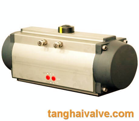
Pneumatic actuator (2)
(3) According to the law of action, actuators can be divided into three types: switch type, integral type and proportional type.
(4) According to the input control signal, the actuator can be divided into several types, such as air pressure signal, direct current signal, electric contact on-off signal, pulse signal, etc.
The working principle of valve actuator:
In the gear stage, the engine speed can be transmitted to the output rod through two sets of gears. The main reducer is completed by planetary gears, and the auxiliary reducer is realized by worm gears, which are fixed in the center by a set of tight springs. In the event of an overload, that is, when the output rod exceeds the set torque of the spring, the central worm gear will undergo axial displacement, and the switches and
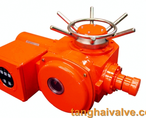
electric actuator for valve
signal devices will be fine-tuned to provide protection for the system. The output rod is coupled with the worm gear when the engine is working, and is coupled with the hand wheel when it is manually operated, under the action of the coupling operated by the external change control lever. When the engine is not working, the motor drive can be easily cut off, and the handwheel can be connected by simply pressing the lever. Since the motor drive takes
precedence over manual operation, when the engine restarts, the reverse action will automatically occur. This can avoid turning on the hand wheel when the engine is running, which is beneficial to protect the system.
Since the hand wheel is directly coupled with the output rod, it can ensure the normal manual operation of the valve when the internal gear fails or is damaged.
The switch and signal device installed on the gear is a sealed shell, which protects its internal components to achieve
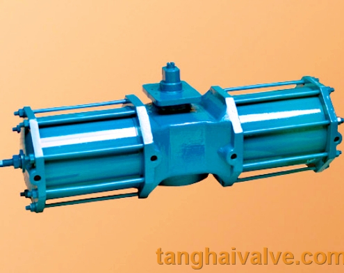
hydraulic actuator for marine valve
the following functions:
- Local or remote display of valve position
- Actuator/valve overload protection
- Limit valve stroke range
- Electrical interface
The installation of valve actuators on different types of valves is completed by the output rod, which can be applied to various existing valve rod configurations.
") tanghaivalve.com
tanghaivalve.com
