The bevel gear is used to transmit the movement and power between the two intersecting shafts. In general
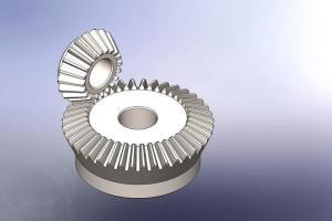
bevel gear
machinery, the angle of intersection between the two shafts of the bevel gear is equal to 90° (but it may not be equal to 90°). Similar to cylindrical gears, bevel gears have indexing cones, addendum cones, tooth root cones and base cones. The cone has a big end and a small end, and the circle corresponding to the big end is called the index circle (its radius is r), the addendum circle, the root circle and the base circle. The movement of a pair of bevel gears is equivalent to a pair of pitch cones for pure rolling.
Application field
Industrial transmission equipment, vehicle differential
Classification
Straight tooth, helical tooth, curved tooth
Features
Noise reduction, shock absorption, light weight, low cost, etc.
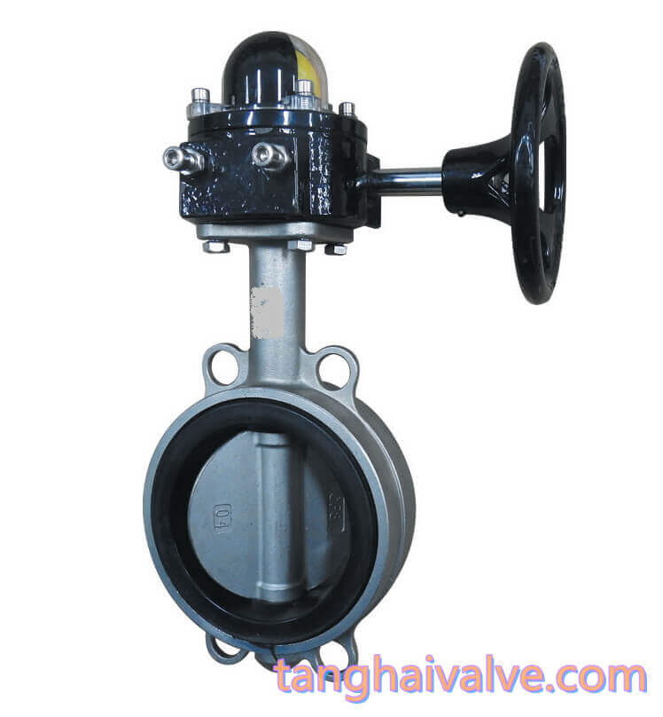
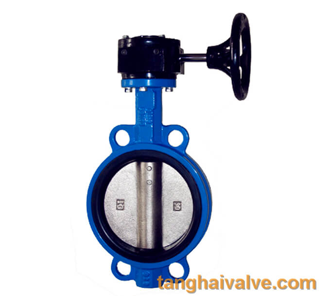
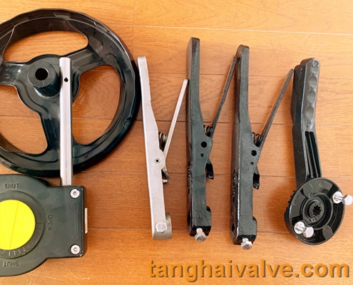
Bevel gear actuator is coded 5 in the valve naming system in China, see link: https://www.tanghaivalve.com/valve-model-establishment-and-meaning/
Unit One , valve type (code name):
| butterfly valve |
safety valve |
Diaph-ragm valve |
ball valve |
gate valve |
check valve |
plug valve |
Pressure reducing valve |
globe valve |
filter |
Disch-arge valve |
| D |
A |
G |
Q |
Z |
H |
X |
Y |
J |
GL |
FL |
Unit two, valve drive mode (code name):
| drive mode |
Electro-magne-tism |
Electro-magnetic hydraulic |
Electro-hydraulic |
tur-bine |
Spur gear |
Bevel gear |
pneu-matic |
Hydr-aulic |
Gas-hydr-aulic |
elec-tric |
han-dle |
Hand-wheel |
| code |
0 |
1 |
2 |
3 |
4 |
5 |
6 |
7 |
8 |
9 |
|
|
Unit three, valve connection method (code name):
| connection |
internal thread |
external thread |
two different connections |
flange |
welding |
wafer |
clamp |
ferrule |
| code |
1 |
2 |
3 |
4 |
6 |
7 |
8 |
9 |
1. Formation of tooth profile
The formation of the tooth profile of bevel gears is similar to that of cylindrical gears, except that the base cone is
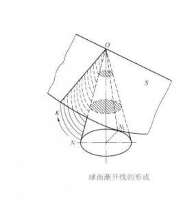
The formation of spherical involute
used instead of the base cylinder. As shown on the right, the generating surface S is tangent to the generatrix of the base cone. When the generating surface S is purely rolling along the base cone, any straight line OK on the
generating surface contacting the generatrix ON of the base cone will form an involute curved surface in space. This curved surface is the tooth profile curved surface of the straight bevel gear. The trajectory of each point on the line OK is an involute (the involute at the vertex O is a point). Each point on the involute NK is equidistant from the cone O, so the involute must be on a spherical surface centered on the cone O and the radius is OK, that is, NK is a spherical involute.
2. Back cone and equivalent gear
The following figure shows a pair of special bevel gear drives. Among them, the number of teeth of wheel 1 is, the indexing circle radius is, and the reference cone angle is; the number of teeth of wheel 2 is, the indexing circle radius is, the indexing cone angle=90°, and the indexing cone surface is A plane, this kind of gear is called a crown gear.
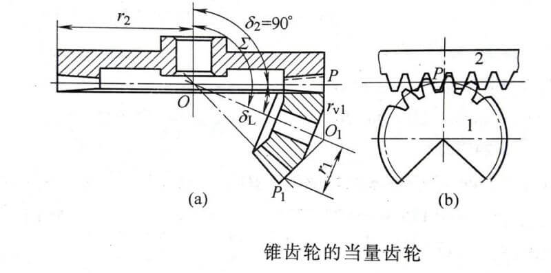
Equivalent gear of bevel gear
The large end node P of the wheel 1 is used as the vertical line of the indexing cone generatrix OP, crossing its axis and point O1, and then taking O1 point as the cone tip and O1P as the generatrix, making a cone tangent to the large end of wheel 1 , Call this cone the back cone of wheel 1. In the same way, the back cone of wheel 2 can be made. Since wheel 2 is a crown wheel, its back cone becomes a cylindrical surface. If the back cones of the two wheels are expanded, the back cone of wheel 1 will be expanded into a sector gear, and the back cone of wheel 2 will be expanded into a rack, that is, after the back cone is expanded, the two are equivalent to gears and teeth. Strip meshing transmission. According to the Fan Cheng principle, when the tooth profile of the rack (that is, the back cone of the crown wheel) is a straight line, the tooth profile of the wheel 2 on the back cone is an involute.
Imagine filling up the gap of the unfolded sector gear, and you will get a cylindrical gear. This imaginary cylindrical gear is called the equivalent gear of the bevel gear, and the number of teeth Zv is called the equivalent number of teeth of the bevel gear. The tooth profile of the equivalent gear and the tooth profile of the bevel gear on the back cone (that is, the big end tooth profile) are consistent, so the modulus and pressure angle of the equivalent gear are consistent with the modulus and pressure angle of the large end of the bevel gear. As for the equivalent number of teeth, it can be obtained as follows:
As can be seen from the figure above, the index circle radius of the equivalent gear of wheel 1 is
γv1=γ1/cosδ1=z1m(2cosδ1)
So
zv1=z1/cosδ1
For any bevel gear there is
zv=z/cosδ
With the help of the concept of bevel gear equivalent gear, the correct meshing condition of a pair of bevel gears should be that the modulus and pressure angle of the large ends of the two wheels are equal respectively; the coincidence degree of a pair of bevel gear transmission can be calculated approximately according to the coincidence degree of the equivalent gear transmission ; In order to avoid undercutting of gear teeth, the minimum number of teeth for bevel gears without undercutting zmin=zvmincosδ
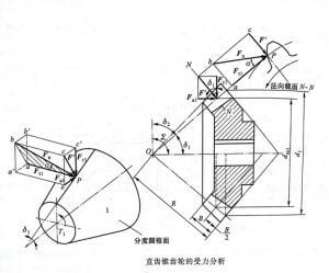
3. Analysis of gear tooth force
Similar to the cylindrical gear, the nominal normal load Fn is decomposed into the circumferential force Ft1, the radial force Fr1 and the axial force Fa1 at the average index circle of the pinion gear. The direction of each force is shown in the figure on the right, and then according to the force balance The geometric relationship between the conditions and the forces is calculated, namely
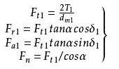
bevel gear force analysis
Force Analysis of Straight Bevel Gear
The force analysis on the big gear is similar to that on the small gear.
4. Geometric parameters and calculations
Bevel gears use the big end parameter as the standard value, so when calculating their geometric dimensions, the big end should also prevail. As shown in the figure below, the index circle diameters of the two bevel gears are respectively
d1=2Rsinδ1, d2=2Rsinδ2
In the formula, R is the distance from the tip of the indexing cone to the large end, which becomes the cone distance; δ1 and δ2 are the indexing cone angles of the two bevel gears (referred to as the cone angle for short).
The transmission ratio of the two wheels is
i12=w1/w2=z2/z1=d2/d1=sinδ2/sinδ1
When the shaft angle Σ=90° between the two bevel gears, the above formula becomes due to δ1+δ2=90°
i12=w1/w2=z2/z1=d2/d1=cotδ1=tanδ2
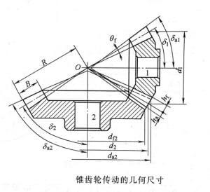
Geometry of bevel gear transmission
When designing bevel gear transmission, the value of the cone angle of the two wheels can be determined according to the above formula according to the given transmission ratio.
As for the size of the bevel gear tip cone angle and the tooth root cone angle, they are related to the head clearance requirements of the two bevel gears when they are meshed and driven. According to national standards (GB/T 12369-1990, GB/T12370-1990), equal head-clearance bevel gears are now used for transmission. The head clearance of the two wheels is equal from the big end to the small end of the gear. The cones of the degree cone and the root cone coincide at one point. However, because the generatrix of the tooth tip cone of the two wheels is parallel to the generatrix of the tooth root cone of the other bevel gear meshing with it, the cone tip no longer coincides with the indexing cone cone tip. This kind of bevel gear is equivalent to reducing the tooth tip height of the small end of the tooth, thereby reducing the possibility of the tooth tip being too sharp; and the tooth root fillet radius is larger, which is beneficial to improve the load capacity of the tooth, tool life and storage Oil lubrication.
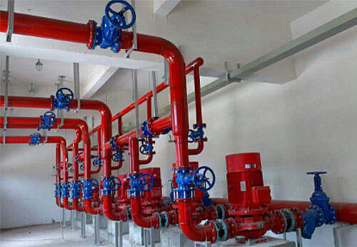
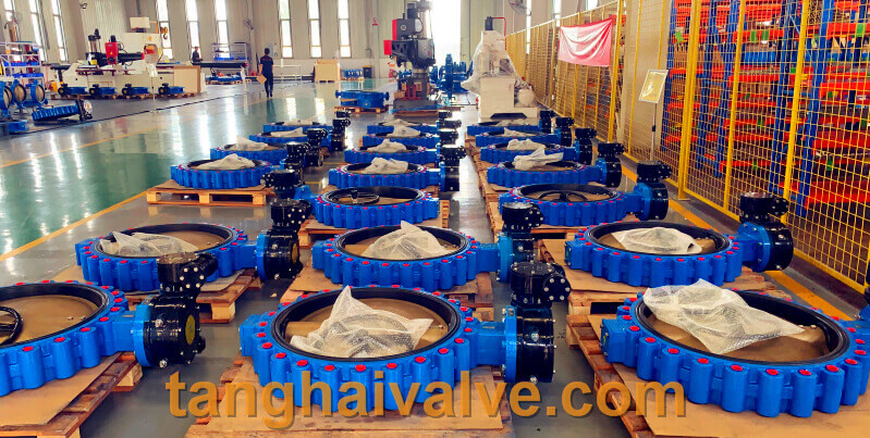
TH Valve is a professional manufacturer of butterfly valve, gate valve, check valve, globe valve, knife gate valve, ball valve with API, JIS, DIN standard, used in Oil, Gas, Marine industry, Water supply and drainage, fire fighting, shipbuilding, water treatment and other systems, with Nominal Diameter of DN50 to DN1200, NBR/EPDM/VITON, Certificates & Approvals: DNV-GL, Lloyds, DNV, BV, API, ABS, CCS. Standards: EN 593, API609, API6D
Related news/knowledge:
Form and types of Gear transmission
What is the positive transmission of gears
what is Spur gear?
What is the gear modification coefficient