Classification and characteristics of welding
Metal welding can be divided into three categories: fusion welding, pressure welding and brazing according to the characteristics of the process. The characteristics are:
1. Fusion welding: heat the workpiece to be joined to partially melt it to form a molten pool. The molten pool will be joined after cooling and solidification. If necessary, a filler can be added to assist. It is suitable for welding of various
welding
metals and alloys without pressure. .
2. Pressure welding: The welding process must apply pressure to the weldment, which belongs to the processing of various metal materials and some metal materials.
3. Brazing: Use metal materials with a lower melting point than the base material as the brazing filler metal, and use the liquid brazing filler metal to wet the base material, fill the joint gap, and mutually diffuse with the base metal to realize the connection of the weldment. Suitable for welding of various materials, and also suitable for welding of different metals or dissimilar materials.
Welding equipment can be divided into manual welding equipment and automatic welding equipment according to the degree of welding automation.
During the welding process, if the atmosphere is in direct contact with the high-temperature molten pool, the oxygen in the atmosphere will oxidize metals and various alloying elements. Nitrogen and water vapor in the atmosphere enter the molten pool, and will also form pores, slag inclusions, cracks and other defects in the weld during the subsequent cooling process, which will deteriorate the quality and performance of the weld.
There are many energy sources for modern welding, including gas flame, electric arc, laser, electron beam, friction and ultrasonic. In addition to being used in factories, welding can also be carried out in a variety of environments, such as the field, underwater and space.
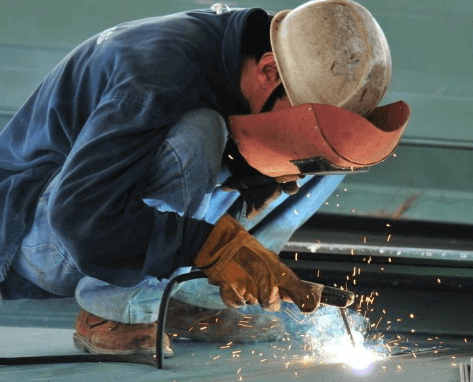
No matter where it is, welding may bring danger to the operator, so appropriate protective measures must be taken when welding. The possible harm caused by welding to the human body includes burns, electric shocks, visual impairment, inhalation of toxic gases, and excessive ultraviolet radiation.
In order to improve the welding quality, various protection methods have been developed. For example, gas shielded arc welding is to isolate the atmosphere with argon, carbon dioxide and other gases to protect the arc and molten pool rate during welding.
For example, when welding steel, adding ferro-titanium powder with high oxygen affinity to the electrode coating for deoxidation can protect the beneficial elements such as manganese and silicon in the electrode from oxidation and enter the molten pool. After cooling, high-quality welds can be obtained.
The common feature of various pressure welding methods is to apply pressure during the welding process without adding filler materials. Most pressure welding methods, such as diffusion welding, high frequency welding, cold pressure welding, etc., do not have a melting process, so there is no problem like fusion welding, which has beneficial alloying elements burning and harmful elements intruding into the weld, thus simplifying the welding process. It also improves welding safety and health conditions.
At the same time, because the heating temperature is lower than that of fusion welding and the heating time is shorter, the heat affected zone is small. Many materials that are difficult to weld by fusion welding can often be welded by pressure welding to form a high-quality joint with the same strength as the base metal.
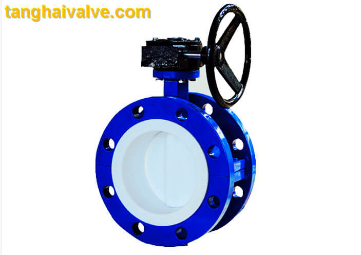
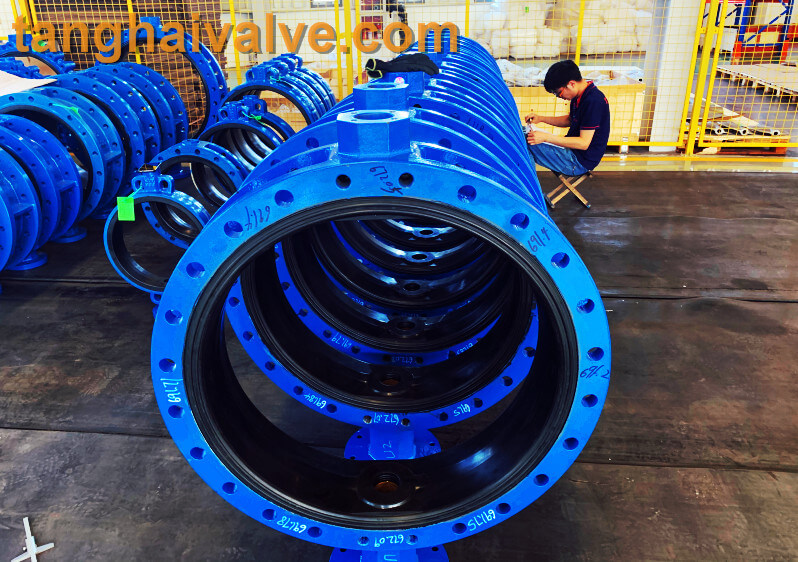
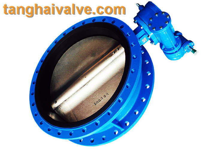
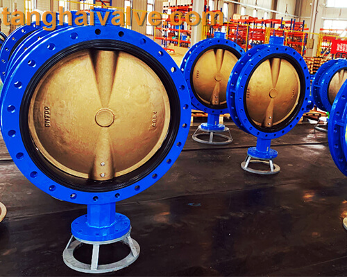
TH Valve is a professional manufacturer of butterfly valve, gate valve, check valve, globe valve, knife gate valve, ball valve with API, JIS, DIN standard, used in Oil, Gas, Marine industry, Water supply and drainage, fire fighting, shipbuilding, water treatment and other systems, with Nominal Diameter of DN50 to DN1200, NBR/EPDM/VITON, Certificates & Approvals: DNV-GL, Lloyds, DNV, BV, API, ABS, CCS. Standards: EN 593, API609, API6D
Related news/knowledge:
What is butt welding? (7)- Flash butt welding of common metals;
What is butt welding? (6)- Flash butt welding of common metals;