How to choose a valve in the chemical industry
The media transported in various pipelines in the chemical industry are usually corrosive, such as sulfuric acid, hydrochloric acid, nitric acid and other corrosive media. All corrosion protection is the most basic requirement of chemical equipment. Chemical valves are of course no exception, and the selection of valve materials must be corrosion-resistant. If the chemical valve is wrongly selected, it will damage the equipment at the slightest level, or cause serious accidents, causing injury to machinery, equipment and even people. However, for different corrosive media, the selection of valves is also different. This article will talk about the key points of valve material selection for some common chemical media:
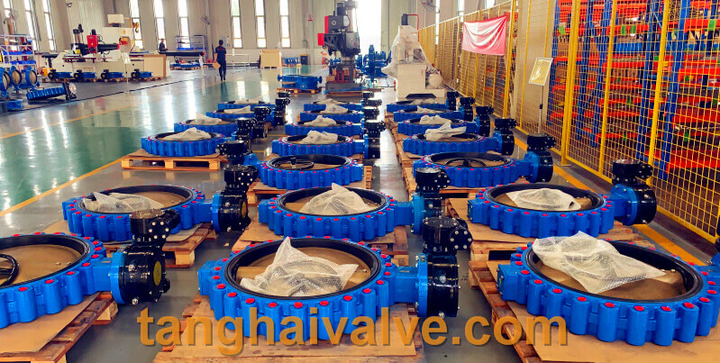
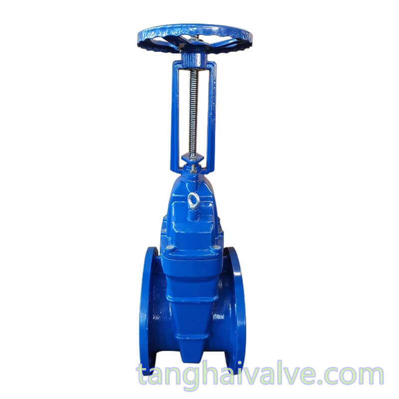
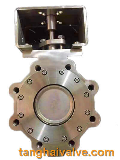
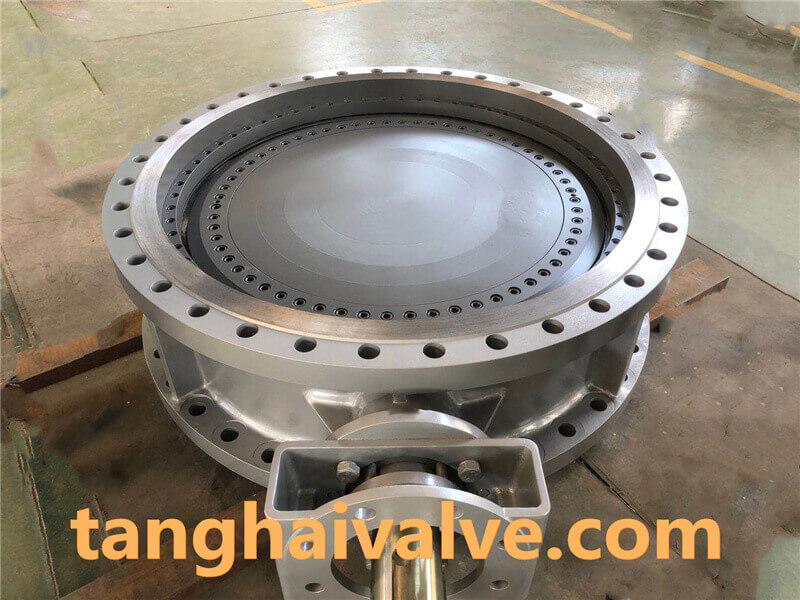
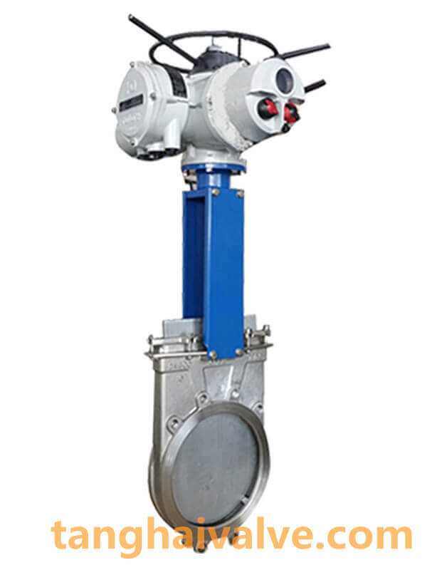
lug type butterfly valve, ductile iron, center lined,
Hydrochloric acid: Most metal materials, including various stainless steel materials, are not resistant to hydrochloric acid corrosion, and high-silicon ferro-molybdenum can only be used in hydrochloric acid below 50°C and 30%. Contrary to metal materials, most non-metal materials have good corrosion resistance to hydrochloric acid, so rubber-lined valves (such as fluoroplastics, etc.) are the best choice for transporting hydrochloric acid. But if the temperature of the medium exceeds 150°C, or the pressure is greater than 16 kg, any plastics (including fluoroplastics and even polytetrafluoroethylene) will be difficult to handle. For hydrochloric acid exceeding this condition, there is no ideal valve currently on the market.
Sulfuric acid: As one of the strong corrosive media, sulfuric acid is an important industrial raw material with a wide range of uses. Different concentrations and temperatures of sulfuric acid have great differences in the corrosion of materials. For concentrated sulfuric acid with a concentration of more than 80% and a temperature of less than 80°C, carbon steel and cast iron have good corrosion resistance, but it is not suitable for high-speed flowing sulfuric acid. Not suitable for use as a valve material; ordinary stainless steels such as 304 and 316 have limited use for sulfuric acid media. Therefore, pump valves for transporting sulfuric acid are usually made of high-silicon cast iron (difficult to cast and process) and high-alloy stainless steel (20 alloy valve). Fluoroplastics have better resistance to sulfuric acid, and fluorine-lined valves (recommended by Tanghai Valves) are a more economical choice. If the pressure is too high and the temperature rises, the point of use of the plastic valve will be impacted, and you can only choose the more expensive ceramic ball valve.
Nitric acid: Most metals are rapidly corroded and destroyed in nitric acid. Stainless steel is the most widely used nitric acid resistant material. It has good corrosion resistance to all concentrations of nitric acid at room temperature. Note that stainless steel containing molybdenum (such as 316, The corrosion resistance of 316L) to nitric acid is not better than that of ordinary stainless steel (such as 304, 321), and sometimes even worse.
Acetic acid: Acetic acid is one of the most corrosive substances in organic acids. Ordinary steel will be severely corroded in acetic acid at all concentrations and temperatures. Stainless steel is an excellent acetic acid resistant material. 316 stainless steel containing molybdenum is also suitable for high temperature and rarefied materials. Acetic acid vapor. For demanding requirements such as high temperature and high concentration of acetic acid or other corrosive media, high alloy stainless steel or fluoroplastic pumps can be used.
Salt water/sea water: The corrosion rate of ordinary steel in sodium chloride solution, sea water and salt water is not very high, and generally must be protected by paint; all kinds of stainless steel also have a very low uniform corrosion rate, but may cause local corrosion due to chloride ions. It is usually better to use 316 stainless steel.
TH Valve is a professional manufacturer of butterfly valve, gate valve, check valve, globe valve, knife gate valve, ball valve with API, JIS, DIN standard, used in Oil, Gas, Marine industry, Water supply and drainage, fire fighting, shipbuilding, water treatment and other systems, with Nominal Diameter of DN50 to DN1200, NBR/EPDM/VITON, Certificates & Approvals: DNV-GL, Lloyds, DNV, BV, API, ABS, CCS. Standards: EN 593, API609, API6D
Related news/knowledge:
Main application areas of 10 major types of valves;
Types and selection of electric valves;
Prevention and treatment of valve corrosion;
Uses and characteristics of manual butterfly valve (2)