Check valve refers to a valve whose opening and closing parts are circular discs and rely on its own weight and medium pressure to generate actions to block the back flow of the medium. It is an automatic valve, also known as one-way valve, non-return valve(NSV) or isolation valve. The movement of the disc is divided into lift type and swing type. The lift check valve is similar in structure to the shut-off valve, but lacks the valve stem that drives the disc. The medium flows in from the inlet end (lower side) and flows out from the outlet end (upper side). When the inlet pressure is greater than the sum of the weight of the disc and its flow resistance, the valve is opened. On the contrary, the valve is closed when the medium flows back. The swing check valve has a disc that is inclined and can rotate around the axis, and the working principle is similar to that of the lift check valve. The check valve is often used as the bottom valve of the pumping device to prevent the backflow of water. The combination of check valve and stop valve can play a role of safety isolation. The disadvantage is that the resistance is large and the sealing performance is poor when closed.
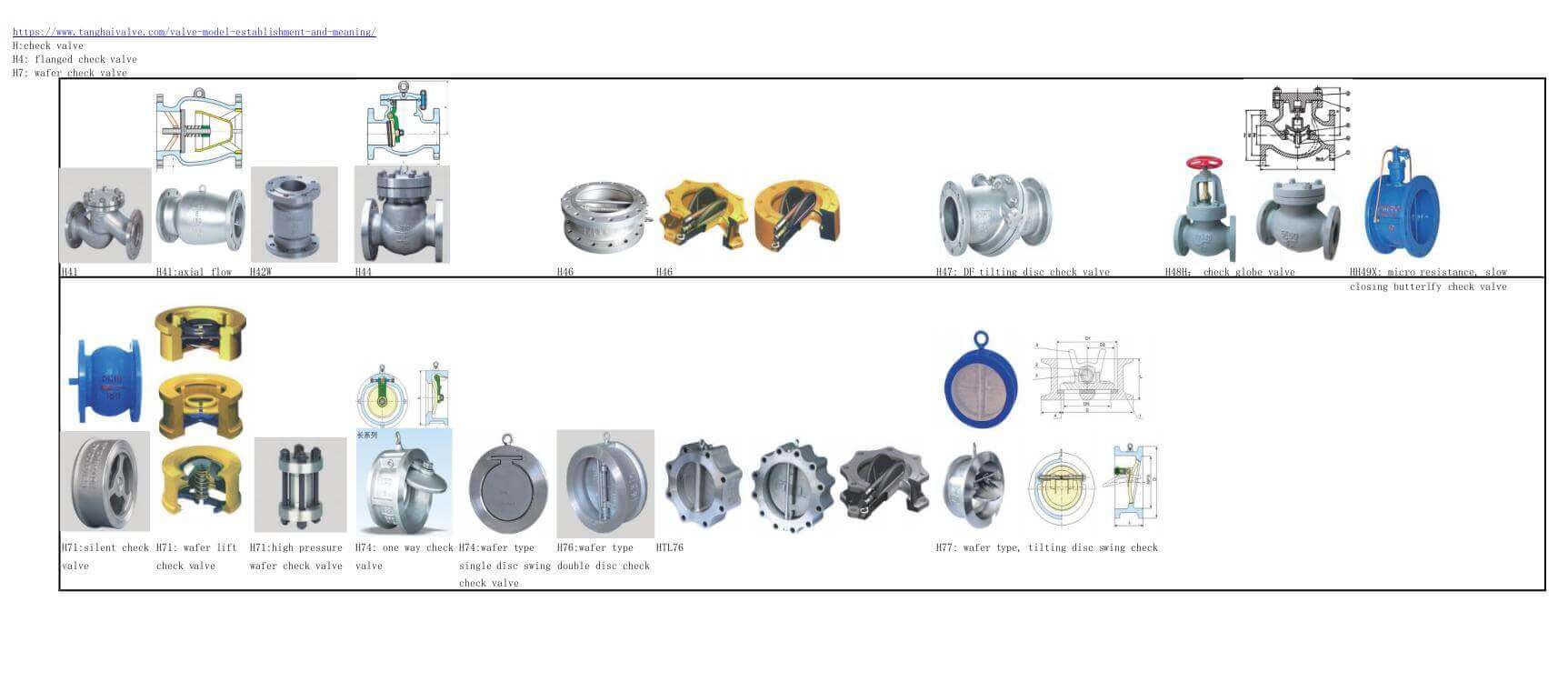
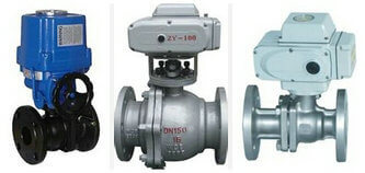
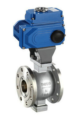
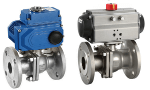
all types of check valve and structures -code names-photos
The working principle of the check valve:
Check valves can also be used to supply pipelines for auxiliary systems where the pressure may rise above the system pressure. Check valves can be divided into swing check valves (rotating according to the center of gravity) and lift check valves (moving along the axis).
The function of this type of check valve is to only allow the medium to flow in one direction and prevent the flow in the opposite direction. Usually this kind of valve works automatically. Under the action of the fluid pressure flowing in one direction, the valve flap opens; when the fluid flows in the opposite direction, the fluid pressure and the self-coincidence of the valve flap act on the valve seat, thereby cutting off the flow.
Among them, the check valve belongs to this type of valve, which includes swing check valve and lift check valve. The swing check valve has a hinge mechanism and a valve disc like a door that rests freely on the inclined valve seat surface. In order to ensure that the valve clack can reach the proper position of the valve seat surface every time, the valve clack is designed in a hinge mechanism so that the valve clack has enough space for rotation and makes the valve clack truly and comprehensively contact the valve seat. The valve clack can be made of metal, leather, rubber, or synthetic covering can be inlaid on the metal, depending on the performance requirements. When the swing check valve is fully opened, the fluid pressure is almost unimpeded, so the pressure drop through the valve is relatively small. The valve disc of the lift check valve is located on the sealing surface of the valve seat on the valve body. Except that the disc can be raised and lowered freely, the rest of the valve is like a shut-off valve. The fluid pressure lifts the disc from the seat sealing surface, and the backflow of the medium causes the disc to fall back onto the seat and cut off the flow. According to the conditions of use, the valve clack can be an all-metal structure, or it can be in the form of a rubber pad or a rubber ring inlaid on the valve clack frame. Like a shut-off valve, the passage of fluid through the lift check valve is also narrow, so the pressure drop through the lift check valve is larger than that of the swing check valve, and the flow rate of the swing check valve is restricted. Rarely.
Classification of check valves:
The valve that opens or closes on its own by the force of the flow of the medium to prevent the medium from flowing back is called a check valve. Check valves belong to the category of automatic valves, which are mainly used in pipelines where the medium flows in one direction, and only allow the medium to flow in one direction to prevent accidents.
Classified by structure:
According to the structure, it can be divided into three types: lift check valve, swing check valve and butterfly check valve:
1. Lift check valves are divided into two types: vertical and horizontal.
2. The swing check valve is divided into three types: single, double and multiple.
3. The butterfly check valve is a straight-through type.
The above check valves can be divided into four types in connection form: threaded connection, flange connection, welding connection and wafer connection.
The selection criteria of the check valve are as follows:
1. In order to prevent the medium from flowing back, check valves should be installed on the equipment, devices and pipelines;
2. Check valves are generally suitable for clean media, not for media containing solid particles and high viscosity;
3. Generally, horizontal lift check valves should be used on horizontal pipes with a nominal diameter of 50mm;
4. The straight-through lift check valve can only be installed in horizontal pipelines;
5. For the inlet pipeline of the water pump, a bottom valve should be used. The bottom valve is generally only installed on the vertical pipeline at the inlet of the pump, and the medium flows from bottom to top;
6. Compared with the swing type, the lifting type has better sealing performance and greater fluid resistance. The horizontal type should be installed on the horizontal pipeline, and the vertical type on the vertical pipeline;
7. The installation position of the swing check valve is not restricted. It can be installed on a horizontal, vertical or inclined pipeline. If installed on a vertical pipeline, the flow direction of the medium should be from bottom to top;
8. The swing check valve should not be made into a small-diameter valve, it can be made into a high working pressure, the nominal pressure can reach 42MPa, and the nominal diameter can also be large, the maximum can reach more than 2000mm. According to the different materials of the shell and the sealing parts, it can be applied to any working medium and any working temperature range. The medium is water, steam, gas, corrosive medium, oil, medicine, etc. The working temperature range of the medium is between -196–800℃;
9. The applicable occasion for swing check valve is low pressure and large diameter, and the installation occasion is restricted;
10. The installation position of the butterfly check valve is not restricted. It can be installed on a horizontal pipeline, or on a vertical or inclined pipeline;
11. Diaphragm check valve is suitable for pipelines that are prone to water hammer. The diaphragm can eliminate the water hammer caused by the reverse flow of the medium. It is generally used on low-pressure and normal temperature pipelines, and is especially suitable for tap water pipelines. Normal media work The temperature is between -12-120℃, and the working pressure is less than 1.6MPa, but the diaphragm check valve can achieve a larger diameter, and the maximum DN can reach more than 2000mm;
12. The spherical check valve is suitable for medium and low pressure pipelines and can be made into a large diameter;
13. The shell material of the spherical check valve can be made of stainless steel, and the hollow sphere of the seal can be wrapped with polytetrafluoroethylene engineering plastic, so it can also be applied to the pipeline of general corrosive media, and the working temperature is -101–150 Between ℃, its nominal pressure is ≤4.0MPa, and the nominal passage range is between DN200-DN1200;
14. When selecting check valves for incompressible fluids, the required closing speed must be evaluated first, and the second step is to select the type of check valve that may meet the required closing speed;
15. The check valve for compressible fluid can be selected according to the similar method of check valve for incompressible fluid. If the medium flow range is large, the check valve for compressible fluid can be used A deceleration device, if the medium flow is stopped and started quickly and continuously, such as the outlet of the compressor, a lift check valve is used;
16. The corresponding size of the check valve should be determined, and the valve supplier must provide the data of the selected size, so that the valve size when the valve is fully opened at a given flow rate can be found;
17. For high and medium pressure check valves below DN50mm, vertical lift check valves and straight-through lift check valves should be used;
18. For low-pressure check valves below DN50mm, butterfly check valves, vertical lift check valves and diaphragm check valves should be used;
19. For high and medium pressure check valves with DN greater than 50mm and less than 600mm, swing check valves should be used;
20. For medium and low pressure check valves with DN greater than 200mm and less than 1200mm, wear-free spherical check valves should be used;
21. For low pressure check valves with DN greater than 50mm and less than 2000mm, butterfly check valves and diaphragm check valves should be used;
22. For pipelines that require relatively small water hammer impact or no water hammer when closed, slow-closing swing check valves and slow-closing butterfly check valves should be selected.
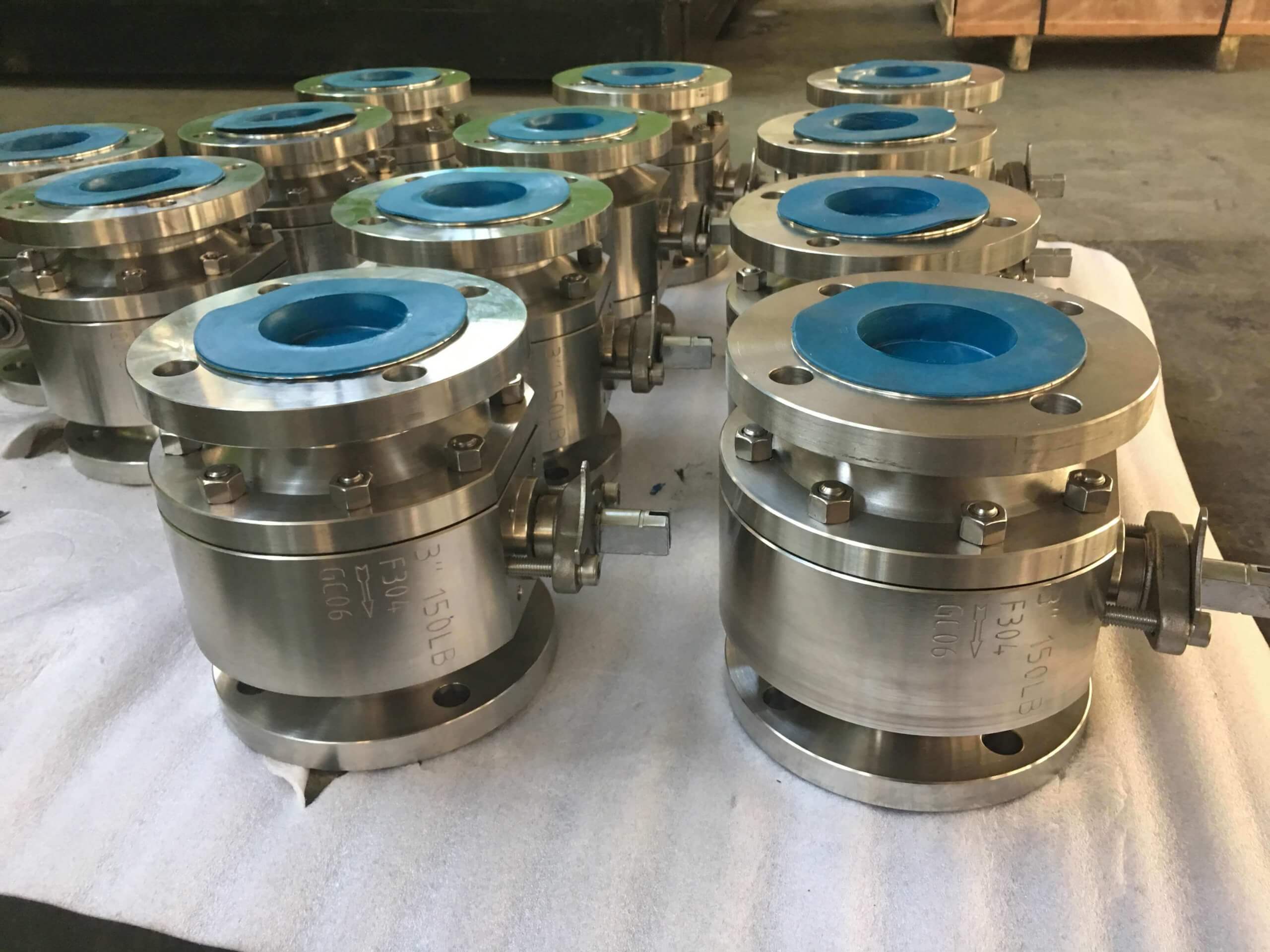
Types of check valves we produce:
We have other types of check valves: single-disc swing check valve, dual plate check valve, tilting disc swing check valve, lift swing check valve, silent check valve and ball check vlave used in Oil, Gas, Marine industry, Water supply and drainage, fire fighting, shipbuilding, water treatment and other systems, with Nominal Diameter of DN50 to DN1200, NBR/EPDM/VITON, Certificates & Approvals: DNV-GL, Lloyds, DNV, BV, API, ABS, CCS. Standards: EN 593, API609, API6D,