Lining material and its application scope of fluorine lined valve
Description of lining material of fluorine-lined valve
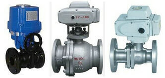
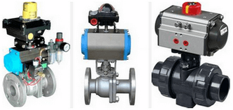
With the maturity of the fluorine lining process, the varieties of fluorine lining valves are becoming more and more
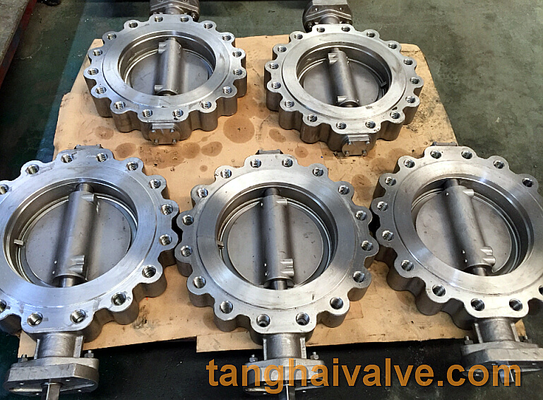
U type flange butterfly valve (3)
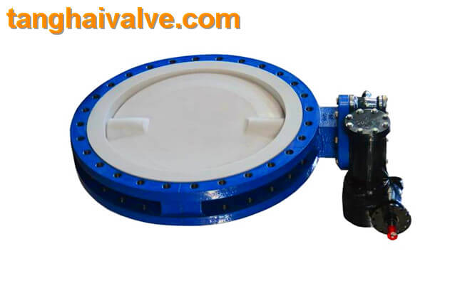
abundant, including fluorine diaphragm valves, fluorine butterfly valves, fluorine ball valves, fluorine check valves, fluorine globe valves, and fluorine filters. The biggest advantage of fluorine-lined valves is to control strong corrosive media, with a pressure rating of 0.6-1.6Mpa, which is suitable for working conditions with a temperature within 150°C. However, there are many types of lining materials for fluorine-lined valves, and different materials are suitable for different media and temperatures. Users should choose the correct type according to the actual working conditions.
| Fluorine-lined valve lining material applicable table | |
| Polyperfluoroethylene FEP (F46) | Applicable medium: any organic solvent or reagent, dilute or concentrated inorganic acid, alkali, ketone, aromatic hydrocarbon, chlorinated hydrocarbon, etc. Operating temperature: -85~150℃ Features: The mechanical, electrical properties and chemical stability are basically the same as F4, but the outstanding advantage is high dynamic toughness, excellent weather resistance and radiation resistance. |
| Polytrifluoroethylene PCTEF(F3) | Applicable medium: various organic solvents, inorganic corrosive liquids (oxidizing acids) Operating temperature: -195~120℃ Features: heat resistance, electrical properties and chemical stability second only to F4, mechanical strength, creep properties, hardness Better than F4 |
| Polypropylene RPP | Applicable medium: aqueous solutions of inorganic salts, dilute or concentrated solutions of inorganic acids and alkalis. Operating temperature: -14~80℃ Features: one of the lightest plastics, its tensile and compressive strength at yield, hardness is better than that of low-pressure polyethylene, outstanding rigidity, good heat resistance, easy to form, and cheap. After modification, it has dynamic impact, fluidity and bending elasticity. |
| Rigid PVC | Applicable medium: water resistant, concentrated alkali, non-oxidizing acid, chain hydrocarbon, oil and ozone, etc. Operating temperature: 0-55℃ Features: high mechanical strength, excellent chemical stability and dielectric properties, good oil resistance and aging resistance, easy welding and bonding, and low price. |
| Polytetrachloroethylene PTFE (F4) | Use medium: strong acid, strong base, strong oxidant, etc. Operating temperature: -200~180℃ Features: Excellent chemical stability, high heat resistance, cold resistance, low friction coefficient, it is an excellent self-lubricating material. But the mechanical properties are low, the fluidity is poor, and the thermal expansion is large. |
| Polyvinylidene chloride PVDF (F2) | Use medium: resistant to most chemicals and solvents, operating temperature: -70~100°C Features: tensile strength and compressive strength are better than F4, bending resistance, weather resistance, and radiation resistance. Light resistance and aging, etc., the biggest feature is good toughness and easy forming. |
| Polyolefin PO | Applicable medium: various concentrations of acid-base salts and certain organic solvents. Operating temperature: -58~80℃ Features: It is the most ideal anti-corrosion material in the world at present, and it has been widely used in the lining of large-scale equipment and pipe fittings of rotational molding. |
Related products:
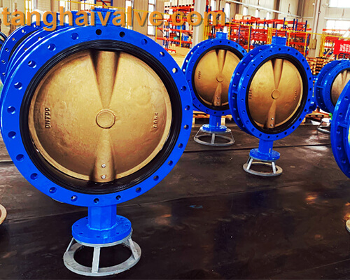
wafer butterfly valve; lug butterfly valve; double flange butterfly valve;
Double eccentric butterfly valve
TH Valve is a professional manufacturer of butterfly valve, gate valve, check valve, globe valve, knife gate valve, ball valve with API, JIS, DIN standard, used in Oil, Gas, Marine industry, Water supply and drainage, fire fighting, shipbuilding, water treatment and other systems, with Nominal Diameter of DN50 to DN1200, NBR/EPDM/VITON, Certificates & Approvals: DNV-GL, Lloyds, DNV, BV, API, ABS, CCS. Standards: EN 593, API609, API6D
Related news/knowledge:
Fluorine-lined valve instructions | Installation instructions;
Code of valve sealing or lining material;
Classification and selection of fluorine-lined valves