Electric globe valve model coding method
Representation method of electric shut-off valve model in China. Globe valve is also called cut-off valve or stop valve.
As a cut-off valve, the electric shut-off valve is the most widely used and one of the most important valves. It is not only suitable for medium and low pressure pipelines, but also for high pressure places, and is relatively durable. It

Globe valve (9)
relies on electric thrust to control the flow of the medium. However, since there are many types of electric shut-off valves and their structural forms are changeable, users should be familiar with the expression method of their model preparation when choosing electric shut-off valves, so as to avoid problems such as selecting the wrong type, replacing goods and returning goods!
The description of the electric shut-off valve model is represented by the code of the shut-off valve type, drive mode, connection mode, structure form, sealing material, nominal pressure, valve body material, etc., mainly for the model description of the existing electric shut-off valve products, such as customized When the material and structure of the globe valve products change, please select according to the valve preparation method.
The method of preparing the model of the electric shut-off valve:
Additional code for stop valve: W: means bellows, D: means low temperature, B: means heat preservation;
1) Type code of globe valve: J: means globe valve;
2) Stop valve transmission mode: manual without code, 5: bevel gear, 6: pneumatic, 9: electric;
3) Connection mode of stop valve: 4: flange connection, 6: welding;
4) The structure of the globe valve: 1 straight-through type, 2 Z-type straight-through, 3 three-way, 4-angle type, 5 Y-type DC type, 6 balanced straight-through type, 7 balanced angle type, 8-pin type;
5) Seal material of globe valve: F: fluorine rubber, H: stainless steel, N: nylon plastic, Y: cemented carbide, M: Monel alloy, W: valve body directly processed;
6) The nominal pressure of the shut-off valve: 16: means that the pressure of 1.6mpa is 16 kilograms, PN1.6-32mpa, IN150LB-1500LB, 5-63K;
7) Globe valve body material: A: titanium alloy, C: carbon steel, I: chromium molybdenum steel, P: stainless steel 304, R: stainless steel 316;
Examples of electric shut-off valve model preparation:
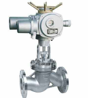
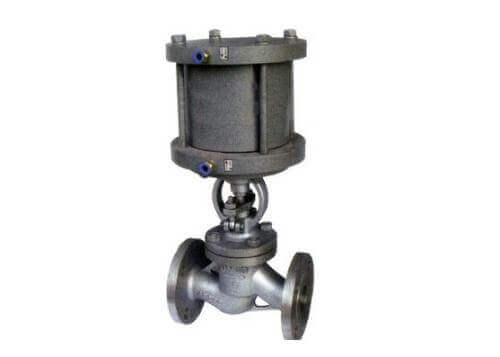
electric globe valve
J941F46-16C Electric flange fluorine-lined globe valve
1. J: indicates the stop valve;
2. 9: indicates that the transmission mode is electric;
3. 4: The connection method is flange connection;
4. 1: The structure is a straight flow channel;
5. F: The sealing material is fluorine rubber;
6. 16: Indicates that the nominal pressure is 1.6MPa;
7. C: Indicates that the valve body material is carbon steel.
TH Valve is a professional manufacturer of butterfly valve, gate valve, check valve, globe valve, knife gate valve, ball valve with API, JIS, DIN standard, used in Oil, Gas, Marine industry, Water supply and drainage, fire fighting, shipbuilding, water treatment and other systems, with Nominal Diameter of DN50 to DN1200, NBR/EPDM/VITON, Certificates & Approvals: DNV-GL, Lloyds, DNV, BV, API, ABS, CCS. Standards: EN 593, API609, API6D
Related news /knowledge: The working principle and characteristics of the globe valve; Representation method of butterfly valve model; Classification of the globe valves-(1);