Commonly used valves for Water Supply and Drainage System
Valves often used in water supply and drainage piping systems include butterfly valve, gate valve, check valve.
This article introduces common water supply and drainage system valves one by one.
1. Butterfly valve: a simple regulating valve, generally used in low-pressure medium pipelines for cutting off and intercepting. It is also one of the common valves in water supply and drainage piping systems. It regulates and intercepts the flow of water on the water supply and drainage pipeline. The butterfly valve is small in size, light in weight, easy to install and operate, but the opening and closing torque is relatively large.

ductile iron, DI, butterfly valve, manufacturer, center line, TH valve
The butterfly valve can be divided into wafer butterfly valve and flange butterfly valve according to the connection mode; according to the different driving mode, it can be divided into handle butterfly valve, turbine butterfly valve, electric butterfly valve, pneumatic butterfly valve, etc.
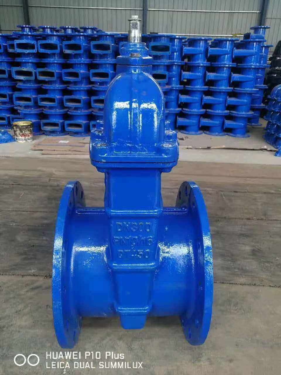
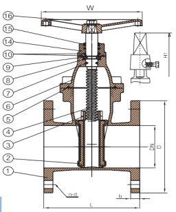
2. Gate valve: It can only be a kind of valve that can cut off the flow of the pipeline medium. The structure of the gate valve is more complicated. It can only be fully opened and fully closed. The opening and closing torque is small, the fluid resistance in the pipeline is small, and it can flow in both directions. The gate valve is most suitable for media that does not contain particles, such as water, because the sealing surface of the gate is easy to wear with impurities or particles in the medium. In addition, impurities precipitate to the bottom of the valve body, which will affect the sealing performance of the gate valve. Causes the defect that the valve is not closed tightly.
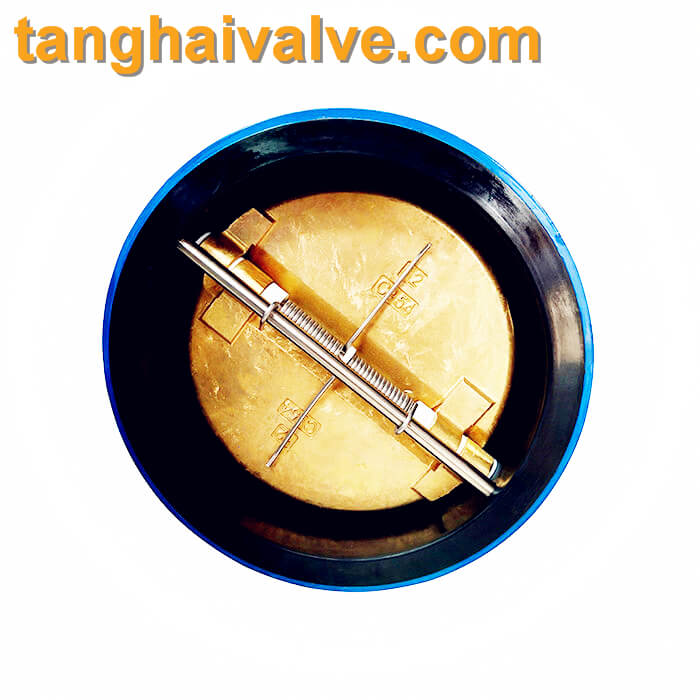
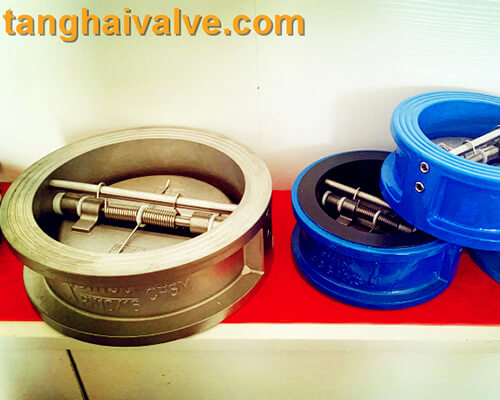
dual plate wafer type check valve (1)
The gate valve is only suitable for use in pipelines that need to be normally open or normally closed, because if the gate valve is frequently opened and closed, it may cause the valve plate to fall off and make the system lose its control ability.
The gate valve can be divided into parallel plate gate valve and wedge plate gate valve according to the difference of the gate. According to the difference of valve stem, it can be divided into open stem gate valve and dark stem gate valve.
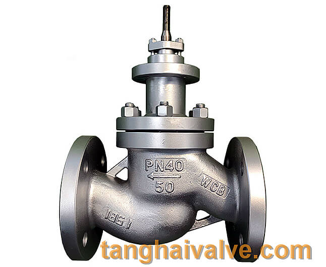
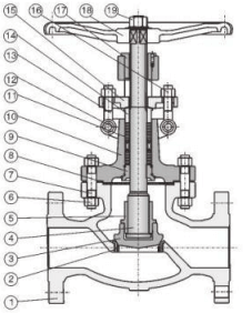
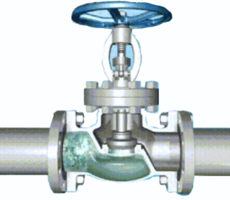
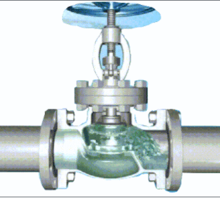
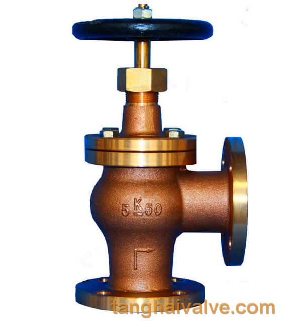
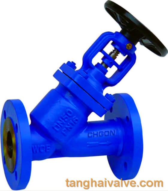
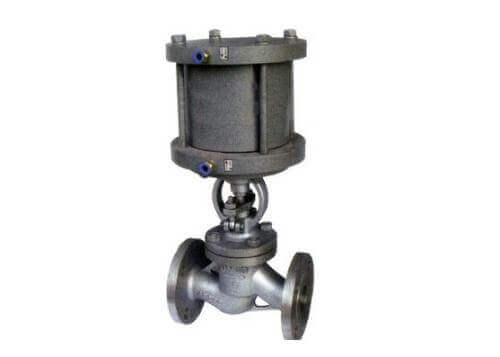
3. Shut-off valve: similar to gate valve, the functions of the two are similar when the medium in the pipeline is cut off. But the difference between the globe valve and the gate valve is that the globe valve has a simpler structure and is more convenient to maintain, but the force used to switch the valve is greater than that of the gate valve. In addition, the globe valve is a one-way valve. When installing, pay attention to the valve body. The instructions on the operation must not be reversed.
4. Check valve: It is also a list valve and check valve, which has strict directio
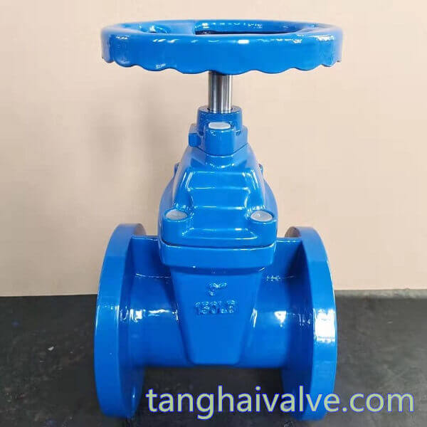
AWWA C509-C515-resilient seated wedge gate valve-DN80-150lb (4)
nality and stipulates that the medium is only allowed to flow in one direction. The check valve is used in pipelines where the medium is water, and is mainly used to prevent backflow of water.
Commonly used check valves include butterfly check valves, muffler check valves, swing check valves and so on. When installing, according to the type of valve, determine whether to install on a vertical pipeline or a horizontal pipeline, and install it strictly in the direction marked by the arrow on the valve body, and the installation cannot be reversed.
TH Valve is a professional manufacturer of butterfly valve, gate valve, check valve, globe valve, knife gate valve, ball valve with API, JIS, DIN standard, used in Oil, Gas, Marine industry, Water supply and drainage, fire fighting, shipbuilding, water treatment and other systems, with Nominal Diameter of DN50 to DN1200, NBR/EPDM/VITON, Certificates & Approvals: DNV-GL, Lloyds, DNV, BV, API, ABS, CCS. Standards: EN 593, API609, API6D
Related news/knowledge:
Wafer type butterfly valve (TH-BTV-AW)
Features and working principle of silent check valve
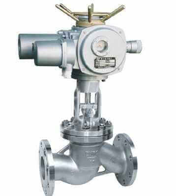
Characteristics and working principle of electric globe valve