The valve is the most used control component in the fluid system. It can be used to switch or control the flow
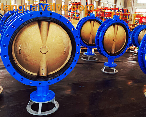
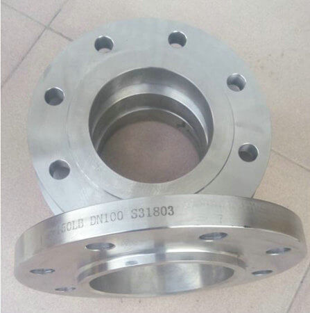
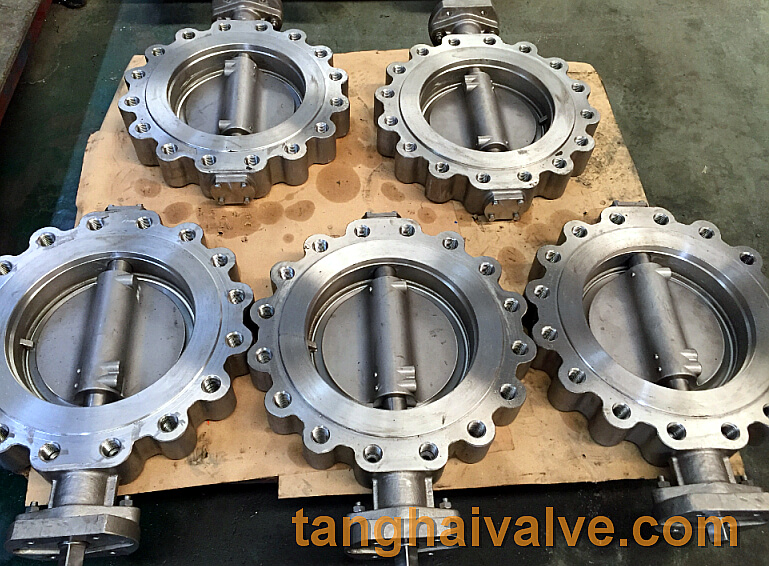
U-type-flange-butterfly-valve-2
direction and adjust the function. From the simplest cut-off function, the valve is sealed in the machine. Its function is to prevent the medium from In the cavity where the part is located, the joint between the parts leaks outward or prevents external substances from entering the inside. The collar and parts that play a sealing role are called seals or sealing structures, or seals for short. The two joint surfaces are in contact with the seal and play a sealing role. The surface is called the sealing surface. The valve sealing surface is the core part of the valve, and its leakage can generally be divided into the following types, namely, leakage of the sealing surface, leakage at the joint of the sealing ring, leakage caused by the fall of the closure member, and leakage of foreign objects embedded between the sealing surfaces. One of the most extensive uses of valves in pipelines and equipment is to cut off the flow of media. Therefore, its tightness is the main factor that determines whether internal leakage occurs. The valve sealing surface is generally composed of a pair of sealing pairs, one on the valve body and the other on the disc.
The reasons for the leakage of the sealing surface are generally as follows:
1. The sealing surface is unevenly ground and cannot form a tight line;
Second, the top center of the connection between the valve stem and the closing member is suspended, incorrect or worn;
3. The valve stem is bent or incorrectly assembled, which makes the closing part skewed or out of alignment;
4. Improper selection of the sealing surface material or failure to select the valve according to the working conditions, the sealing surface is prone to corrosion, erosion and wear;
5. Surfacing and heat treatment are not operated in accordance with the regulations, due to low hardness, wear, corrosion due to burning of alloy elements, and cracks due to excessive internal stress;
Six, the sealing surface after the surface treatment peels off or loses its original performance due to excessive grinding; Seven, the sealing surface is not tightly closed or the crevices appearing due to cold shrinkage after closing, resulting in intermediate corrosion; Eight, treat the shut-off valve as When the throttle valve and pressure reducing valve are used, the sealing surface is eroded and damaged;
9. The valve has reached the fully closed position and continued to apply excessive closing force, including incorrect use of long levers, and the sealing surface was crushed and deformed;
10. Excessive wear of the sealing surface causes disconnection, that is, the sealing pair cannot be tightly sealed;
Prevention and elimination methods of valve sealing surface leakage:
1. When grinding the sealing surface, the grinding tools, abrasives, emery cloth, sandpaper and other objects should use a reasonable grinding method to be correct, and color inspection should be carried out after grinding. The sealing surface should be free of indentation, cracks, scratches and other defects;
2. The connection between the valve stem and the closing member should meet the design requirements. If the top center does not meet the requirements, it should be trimmed. The top center should have a certain movable clearance, especially the axial gap between the valve stem shoulder and the closing member should not be less than 2 Mm;
3. The bend of the valve stem should be straightened. After the valve stem, stem nut, closing parts and valve seat are adjusted, they should be on a common axis;
Fourth, when selecting a valve or replacing the sealing surface, it should meet the working conditions. After the sealing surface is processed, its corrosion resistance, resistance and scratch resistance should be good;
5. The surfacing welding and heat treatment process should meet the technical requirements of the regulations and specifications. After the sealing surface is processed, the acceptance should be carried out. No defects that affect the use are allowed;
Six, the sealing surface surface firing, nitriding, shed infiltration, plating and other processes must be carried out in strict accordance with the technical requirements of its regulations and specifications. The penetration layer of the sealing surface should not exceed one-third of this layer to damage the plating and penetration layer. In serious cases, the plating layer and penetration layer should be removed and the surface treatment should be performed again. The sealing surface of the surface with high frequency smashing can be repeatedly fired and repaired;
Seven, the valve should be marked when it is closed or opened, and it should be repaired in time if the valve is not tightly closed. For high-temperature valves, some slits that appear to be cold-shrinked after closing should be closed more than once at a certain interval after closing;
8. The valve used as a shut-off valve is not allowed to be used as a throttle valve or a pressure reducing valve. The closing part should be in the fully open or fully closed position. When the flow and pressure of the medium need to be adjusted, the throttle valve and reducing valve should be set separately. Pressure valve;
9. The front opening and closing of the valve should comply with the section “Operation of the valve”. The closing force of the valve is appropriate. The diameter of the handwheel is less than 320mm. Only one person is allowed to operate. For handwheels with a diameter equal to or greater than 320mm, two persons or one person are allowed to operate. Operate with leverage within 500 mm;
10. After the waterline drops, it should be adjusted, and the sealing surface that cannot be adjusted should be replaced;
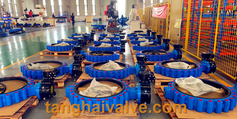
TH Valve is a professional manufacturer of butterfly valve, gate valve, check valve, globe valve, knife gate valve, ball valve with API, JIS, DIN standard, used in Oil, Gas, Marine industry, Water supply and drainage, fire fighting, shipbuilding, water treatment and other systems, with Nominal Diameter of DN50 to DN1200, NBR/EPDM/VITON, Certificates & Approvals: DNV-GL, Lloyds, DNV, BV, API, ABS, CCS. Standards: EN 593, API609, API6D
Related news /knowledge:
Prevention and treatment of valve corrosion;
Application of low temperature butterfly valve;
Valves’ sealing requirements and daily maintenance;
Description of lining material for rubber lining valve.