full bore ball valve vs reduced bore ball valve
The difference and selection of full bore ball valve and reduced bore ball valve
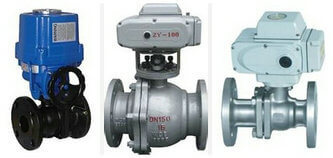
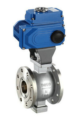
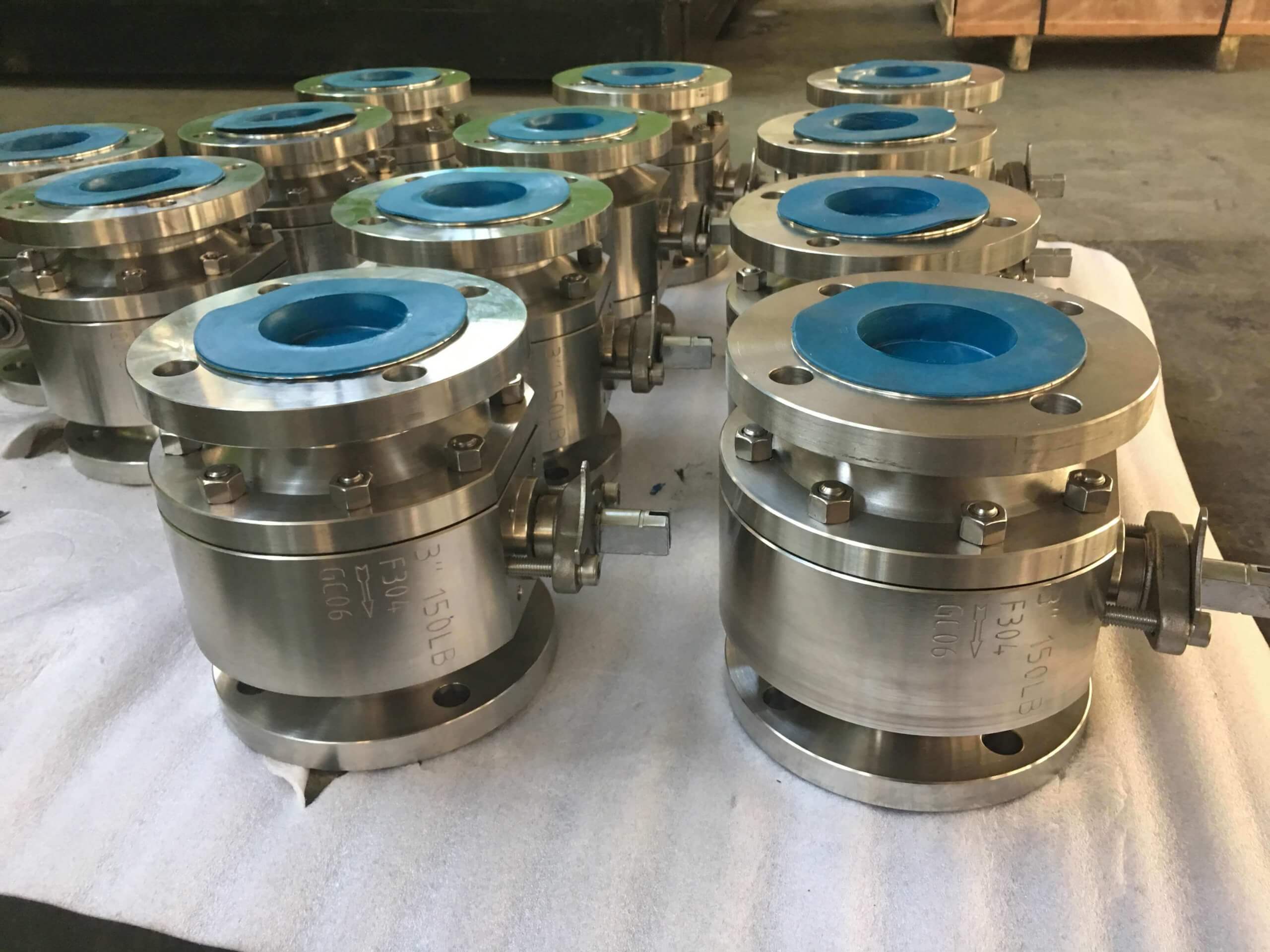
Ball valve is currently the most widely used mechanical product in all valve markets. It is mainly composed of valve body, valve seat, ball, valve stem and transmission device. The ball core is driven to rotate through the actuator to achieve the function of switching or adjusting. . In the chemical industry, environmental protection, water treatment, urban construction, machinery, and food industries, it is widely used and very popular! there are Electric ball valve and Pneumatic ball valve, and other actuated ball valves.
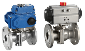
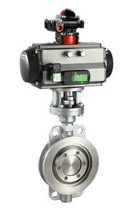
Pneumatic electric high platform ball valve
There are many types of ball valves, which can be combined into various products with different functions through different structures, connection methods, pressure levels, drive forms, etc., but from the most basic point of view, ball valves have two types: full-diameter ball valves and reduced-diameter ball valves. The difference between major categories. Generally speaking, when the inner diameter of the valve ball is less than or equal to 85% of the inner diameter of the ball valve port, it is called a reduced-diameter ball valve, and when the inner diameter of the ball valve is greater than 95% of the inner diameter of the ball valve port, it is called a full-bore ball valve. So what is the difference between the two in the selection or application?
The definition of full bore ball valve and reduced bore ball valve:
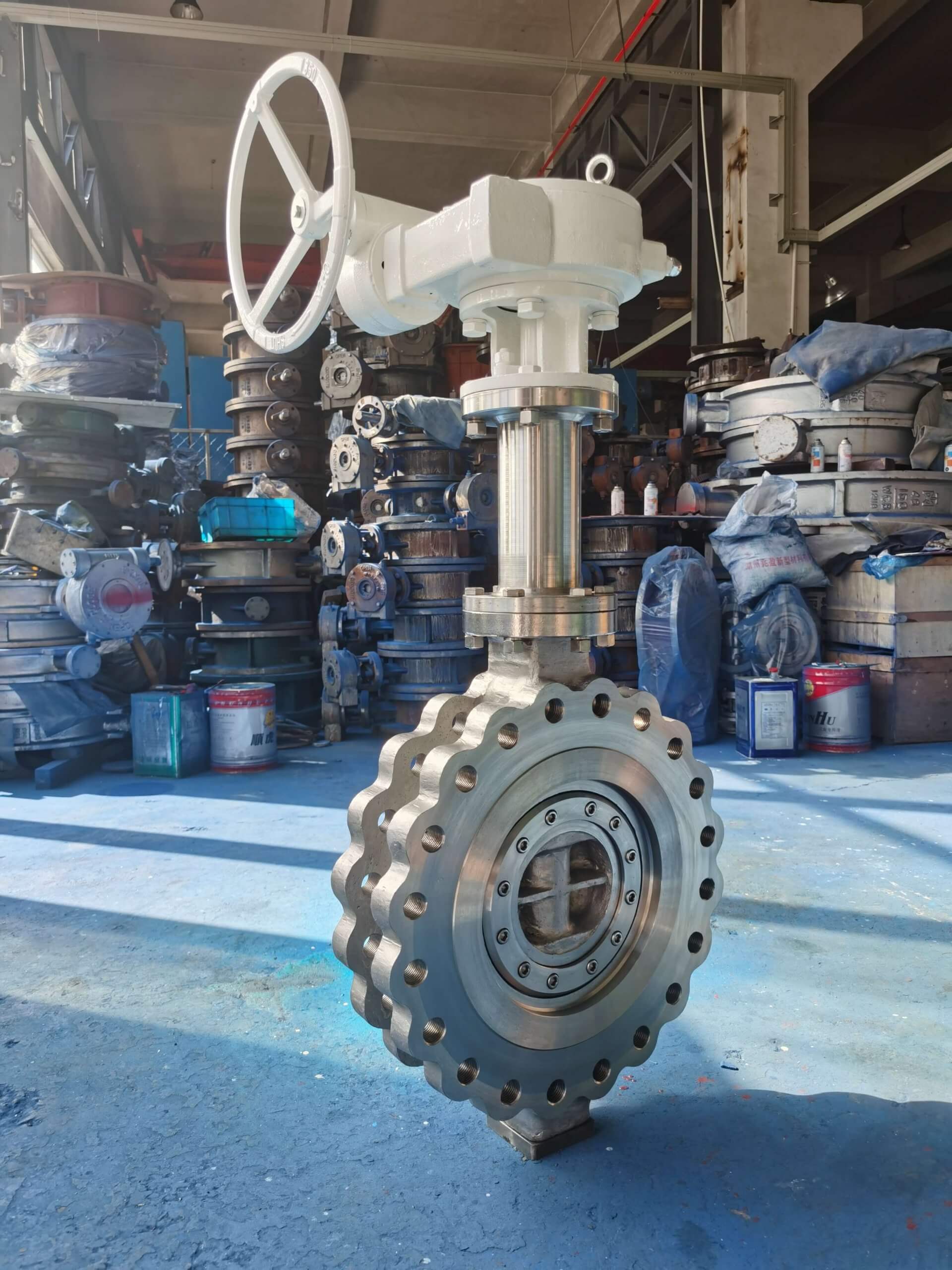
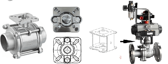
fixed ball valve
1. The full-bore ball valve has equal-width flow channels, that is to say, the size of the orifices from inflow to outflow is the same, and its size cannot be less than the value specified by the standard, which is roughly equivalent to the nominal diameter of the specification, such as DN50 full-diameter The diameter of the ball valve flow path also needs to be about 50;
2. The inlet of the reduced diameter ball valve is wider than the diameter of the flow path, and the actual diameter of the flow path is about one specification smaller than this specification. For example, the diameter of the DN50 reduced diameter ball valve is about 38, which is roughly equivalent to the specification of DN40. One specification is reduced within DN250 and two specifications are reduced from 250-600. Above 600 depends on the actual situation.
Applicable medium for full bore ball valve and reduced bore ball valve:
1. The full-bore ball valve is generally used on pipelines for conveying viscous and slagging media. Because of its low fluid resistance, it can be said that there is basically no flow resistance, and it is convenient for regular wax scrapers to pass through.
2. Reduced diameter ball valve is suitable for conveying gas or pipelines with physical properties similar to water. Because its weight is about 30% lighter than a full-diameter ball valve, and its flow resistance is only 1/7 of that of a stop valve of the same diameter. about. It is helpful to reduce the pipeline load and reduce the cost.
Applicable process for full bore ball valve and reduced bore ball valve:
1. For pipelines that require regular pigging, no matter what kind of medium is transported, full-diameter ball valves must be used. The medium passing through the full-bore ball valve will not reduce the flow, and the flow resistance is small, which is an ideal product for pipeline control, especially for strict working conditions. Especially when the main line in the oil pipeline and gas pipeline needs to be buried underground, full-diameter welded ball valves must be used.
2. The reduced diameter ball valve is suitable for some working conditions such as low requirements and small convection resistance requirements. When the inner diameter of the valve is greater than 80% of the inner diameter of the pipe end, it has almost no effect on the pipeline fluid passing capacity. Many valves have a reduced diameter, which is generally controlled within 0.8. On the one hand, the reduced diameter reduces the flow capacity of the valve, that is, the Kv value of the valve, and increases the pressure drop at both ends of the valve, causing energy loss. That said, there is not much impact, and it may increase the erosion of the pipeline.
The advantages and disadvantages of full-bore ball valves and reduced-bore ball valves are compared:
1. Installation space: The reduced-diameter ball valve has a small volume, so its installation space requirements are smaller. Because its weight is about 30% lighter than a full-diameter ball valve, it is beneficial to reduce the pipeline load, reduce the transportation load and reduce the cost.
2. Cost: Reduced-diameter ball valves are one grade lower than full-diameter ball valves. Considering the cost performance, it is generally accepted internationally that adjacent pipe diameters use the same ball-diameter valve body. For example, dn32 and dn40, dn50 and dn63, dn90 and dn110, dn160 and dn200, dn250 and dn315 use the same sphere.
Note: Since the inner diameter of the reduced diameter ball valve is small, the torque on the valve stem is small, which is more suitable for prolonging the service life of the valve switch. Especially the low-torque design of large-diameter valves. However, the diameter cannot be reduced too much, otherwise the system resistance will increase. However, if the diameter is not reduced, the purchase cost will be increased, and the control characteristics of the valve will generally be reduced, which will make the adjustment effect worse. For example, if the regulating valve is always used at a small opening, the service life of the valve will be reduced.
TH Valve is a professional manufacturer of butterfly valve, gate valve, check valve, globe valve, knife gate valve, ball valve with API, JIS, DIN standard, used in Oil, Gas, Marine industry, Water supply and drainage, fire fighting, shipbuilding, water treatment and other systems, with Nominal Diameter of DN50 to DN1200, NBR/EPDM/VITON, Certificates & Approvals: DNV-GL, Lloyds, DNV, BV, API, ABS, CCS. Standards: EN 593, API609, API6D
Related news /knowledges:
What is a ball valve?;
What is butt welding? (8)- typical workpieces;
electric hard seal butterfly valve vs electric soft seal butterfly valve;
Main application areas of 10 major types of valves;