Is it better to install gate valve or ball valve next to regulating valve?
Because both gate valve and ball valve can be used behind the regulating valve, the functions they undertake are basically similar. The two are only different in structure, so users often have questions about whether the gate valve is better or the ball valve is better. This is exactly what this article will discuss today.
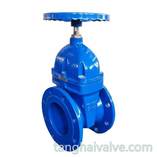
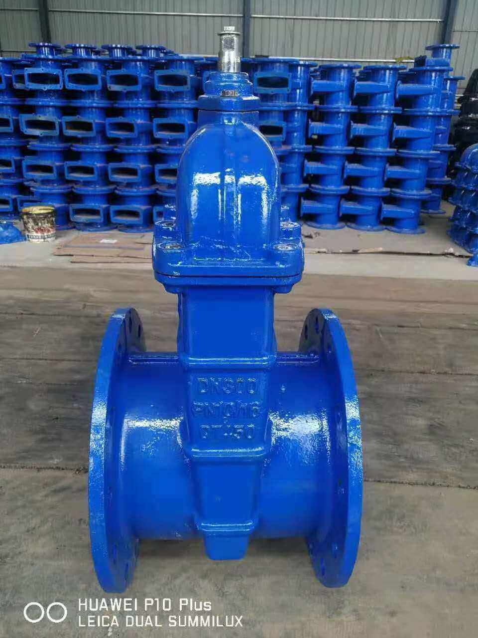
DIN-F4-BB-NRS-soft seated-wedge gate valve-DN100-PN16-copper holding ring-handwheel (3)
Before the problem unfolds, we must first make it clear that there is no concept of which product is better for installing a gate valve or a ball valve before and after the regulating valve. Only the more suitable one can be selected according to the actual situation of the user and the working conditions. Let’s first briefly understand the characteristics of gate valves and ball valves.
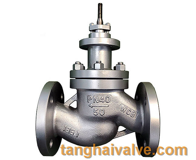
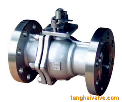
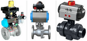
In terms of function, the gate valve can be installed before and after the regulating valve, mainly used for water supply and hot water pipelines, commonly known as water valves. Generally not used on steam pipelines, because when the steam pressure is high, the gate is difficult to open under pressure, and it is also not suitable for use on pipelines with sediment. The sediment accumulates in the ram seat groove, which will cause the gate to close. strict. The opening and closing part of the gate valve is a gate. The movement direction of the gate is perpendicular to the direction of the fluid. The gate valve can only be fully opened and fully closed, and cannot be adjusted or throttled. The ball valve can also be installed before and after the regulating valve. It is mainly used to cut off, distribute and change the flow direction of the medium in the pipeline. It has the same action of rotating 90 degrees. The difference is that the cock body is a sphere with a circular through hole. Or the channel passes through its axis.
In terms of advantages, the more prominent advantages of gate valves are small resistance, short size, and low price. The relative advantage of ball valves is that they have better fluid control characteristics than gate valves. It only
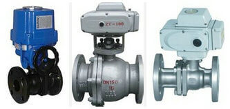
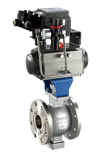
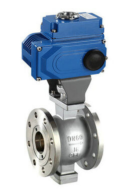
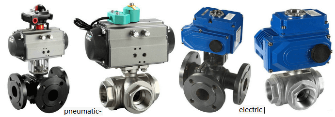
electric ball valve
needs a 90-degree rotation operation and a small torque to close tightly. Ball valves are most suitable for use as on-off and shut-off valves.
From the above we can see that both gate valve and ball valve can be used before and after the regulating valve. Both of these valves are not suitable for flow control, but the ball valve has better fluid control characteristics than the gate valve, and the sealing performance is also better than that of the gate valve. . However, in actual installation cases, although gate valves and ball valves are installed before and after regulating valves, gate valves are more selected by users. This is why? details as follows:
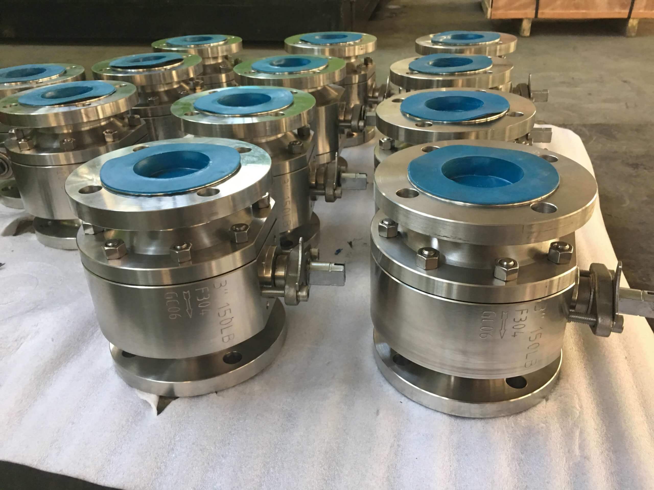
1. It is troublesome to open and close the ball valve, and it has high requirements on the sealing surface. The sealing of the ball valve has strict requirements on the production and processing technology. If the correct manufacturer is not selected, it is easy to cause the internal leakage of the ball valve if the technology cannot meet the requirements. The cost is therefore relatively high, especially for large-caliber ball valves. The gate valve purchase cost is low, the sealing effect is good, the switch is relatively labor-saving, and when the gate valve is fully opened, it can provide the largest flow passage without causing resistance.
2. If the ball valve is in a static state for a long time, it will jam after a period of use.
3. The requirement of the ball valve for the medium is higher than that of the gate valve. For example, with more fibers and oxygen media, only ball valves can be used.
To sum up, whether it is better to install a gate valve or a ball valve before and after the control valve, we conclude that: Consider the economy, use the gate valve, and the gate valve is much cheaper. Or use gate valves on large-caliber, low-pressure oil, steam, and water pipelines. Considering the tightness, use the ball valve. The ball valve is suitable for working conditions with high requirements for leakage, and is suitable for fast opening and closing, and its quality life is better than that of gate valves.
TH Valve is a professional manufacturer of butterfly valve, gate valve, check valve, globe valve, knife gate valve, ball valve with API, JIS, DIN standard, used in Oil, Gas, Marine industry, Water supply and drainage, fire fighting, shipbuilding, water treatment and other systems, with Nominal Diameter of DN50 to DN1200, NBR/EPDM/VITON, Certificates & Approvals: DNV-GL, Lloyds, DNV, BV, API, ABS, CCS. Standards: EN 593, API609, API6D
Related news/knowledge:
How does a butterfly valve work?
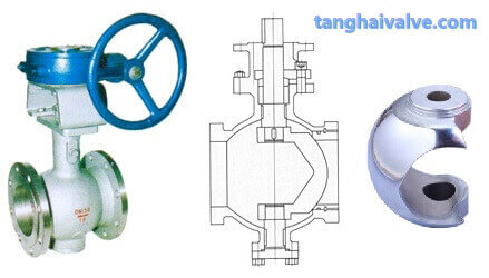
V-type regulating ball valve
Electric ball valve principle | Electric ball valve working principle
What is a ball valve?(