Working principle diagram of three-way valve
What is a three-way valve? Simply put, a three-way valve has three inlets and outlets; when the three-way merges, there are two in and one out, and the three-way split is one in and two out. It is controlled according to the shape of the spool. The most obvious difference in appearance between a three-way valve and a two-way valve is one more flow passage. The three-way valve is mainly used to change the flow direction of the medium. In addition to the inlet A, the outlet B, and the reversing port C, ordinary valves do not have the function of changing the flow direction of the medium.
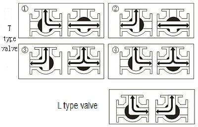
T, L type port valve
Three-way valve structure: Three-way valves are generally divided into L-type and T-type. The T-shape can connect three orthogonal pipelines with each other and cut off the third channel, which can split and merge. The L shape can only connect two orthogonal pipes, and cannot maintain the third pipe to communicate with each other at the same time. It only plays a role of distribution.
Principle of three-way valve:
When the valve opens, the medium enters the valve from A, and flows out of the valve through B. When the bypass requires medium to flow in, the actuator is opened, the valve core is reversed, and medium A enters C out. When the pipeline does not require medium to flow in, the actuator is opened and the valve close Cut off the media.
Three-way solenoid valve:
There are several working positions of the spool. The solenoid valve is called several solenoid valves: the interface on the valve body, which is the number of passages of the solenoid valve, has several passage ports, and the solenoid valve is called a few-way solenoid valve, which means two Position means that there are two working positions that can be switched, and the three-way has three channels for ventilation.
Two-position, two-way, two-position, three-way solenoid valve principle The solenoid valve is one in and one out (two channels); one channel is connected to the air source, and the other channel is connected to the air inlet of the actuator;
Three-way solenoid valve
The two-position three-way solenoid valve controls the gas to be one inlet, one outlet and one exhaust (there are two working positions); one channel is connected to the air source, the other two channels are connected to the air inlet of the actuator, and one Adjacent to the exhaust port of the actuator;
The two-position five-way solenoid valve controls the gas to be one inlet, two outlets and one exhaust (the working position is also two); 1 air inlet (connected to the air source), 1 positive action vent hole and 1 * as a vent hole (Separately provide the target equipment with one positive and one* air source), 1 positive action exhaust hole and 1 *exhaust hole (installation*);
The three-position five-way solenoid valve controls the gas to be one in, two out and one exhaust (but there are three working positions); 1 air inlet (connected to the air source), 1 positive action vent hole and 1 * as a vent hole (Separate the air source provided for the target equipment in one positive and one *), 1 positive action vent and 1 ** vent (installation*).
Principle of three-way solenoid valve:
One in and one out: Normally closed (ZC2/3)—When the solenoid valve coil is energized, port 2 leads to port 1, and port 3 is closed; when the solenoid valve coil is de-energized, port 2 is closed and port 1 leads to Port 3; Normally open (ZC2/3K) When the solenoid valve coil is powered off, port 3 leads to port 1, and port 2 is closed; when the solenoid valve coil is energized, port 3 is closed, and port 1 leads to port 2;
One input and two output: (ZC2/31) When the solenoid valve coil is energized, the first circuit of the medium outlet (2) is opened and the second circuit (3) is closed; when the solenoid valve coil is de-energized, the first circuit of the medium outlet is closed. (2) Close, the second way (3) opens;
Two in and one out: (ZC2/32) When the solenoid valve coil is energized, the first circuit (2) of the medium inlet is opened, and the second circuit (3) is closed; when the solenoid valve coil is de-energized, the first circuit of the medium inlet (2) Close, and the second way (3) opens; (Check valves must be added before the two inlet ends of the inner valve)