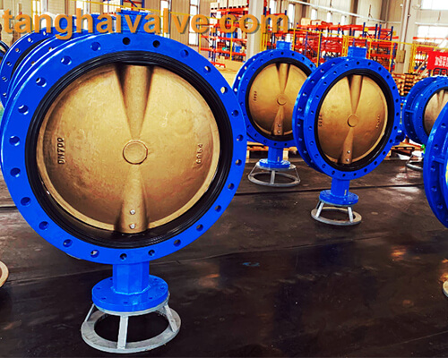
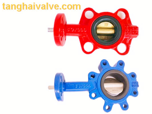
Vulcanized vs soft seated/back-up butterfly valve
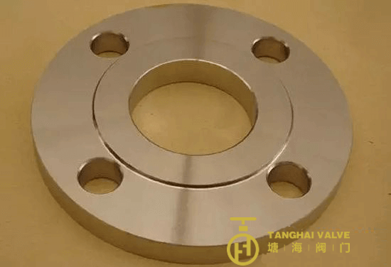
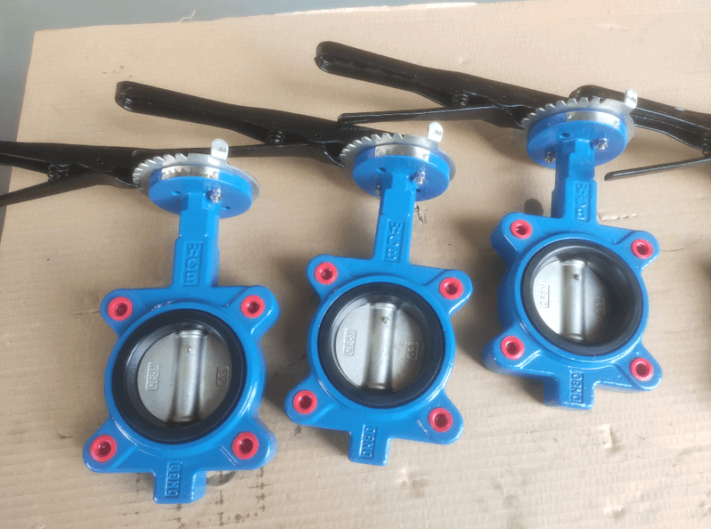
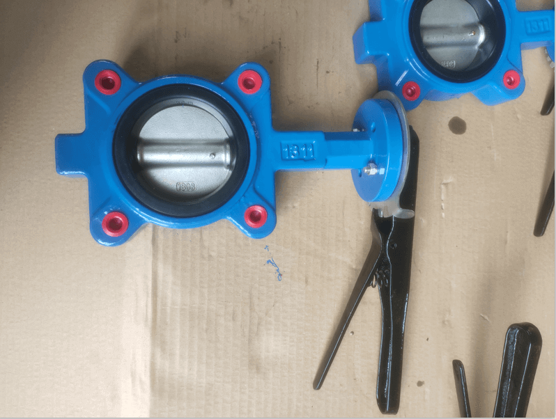
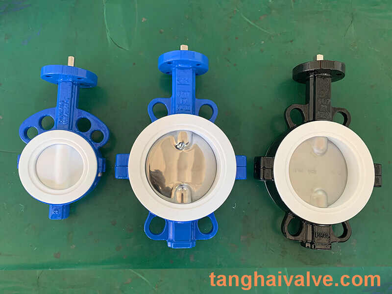
The difference between rubber-lined butterfly valve and rubber butterfly valve (illustration)
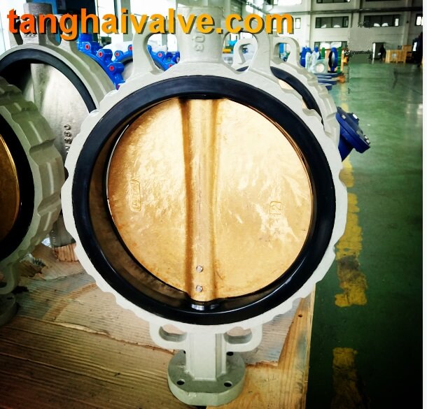
The difference between a rubber-lined butterfly valve and a rubber butterfly valve, and the difference between a rubber-lined butterfly valve and a plastic-lined butterfly valve. The rubber-lined butterfly valve uses a high-temperature method to vulcanize the rubber and the valve body into one body. It has very high corrosion resistance and is generally used. To control some corrosive fluids with strong acidity and alkalinity. The rubber butterfly valve is a butterfly valve whose seal is a rubber seal, which is generally called a valve seat, and is separately installed into a whole.
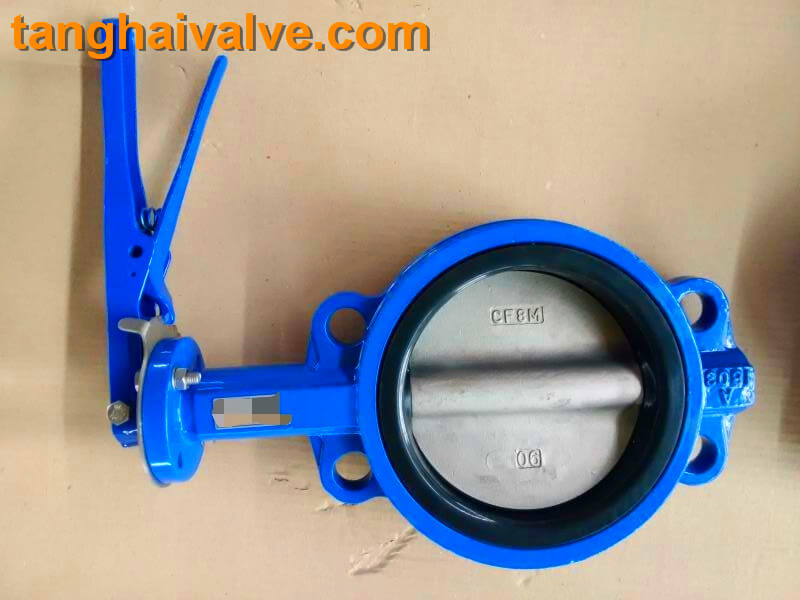
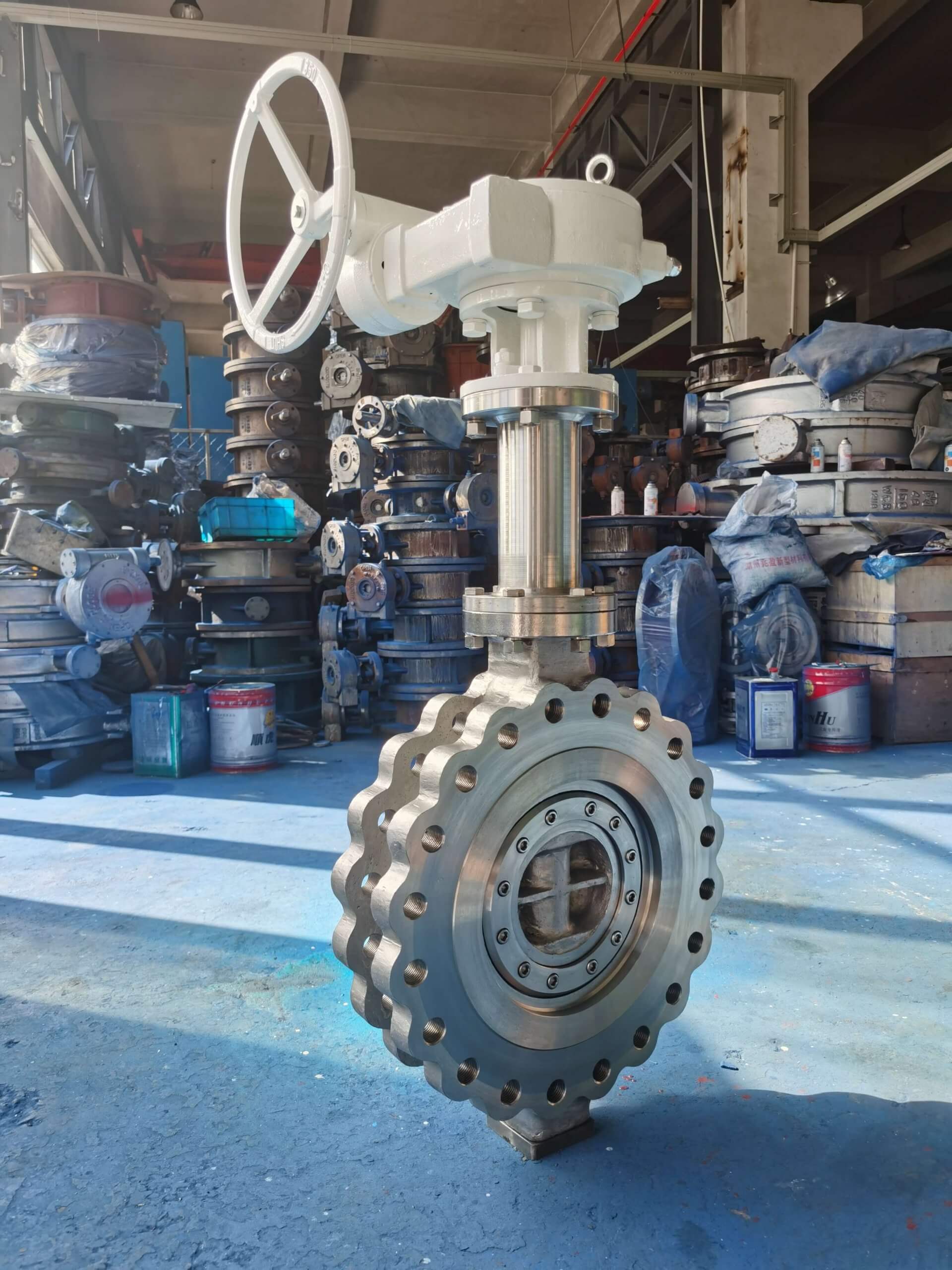
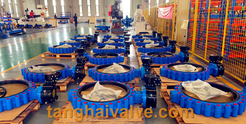
Fluorine lined butterfly valve-PTFE-WAFER (8)
At normal temperature, the abrasion resistance of natural soft rubber is much better than that of nitrile rubber, but their high temperature resistance is the highest limit within 80 degrees, and it is not suitable for use if it exceeds.
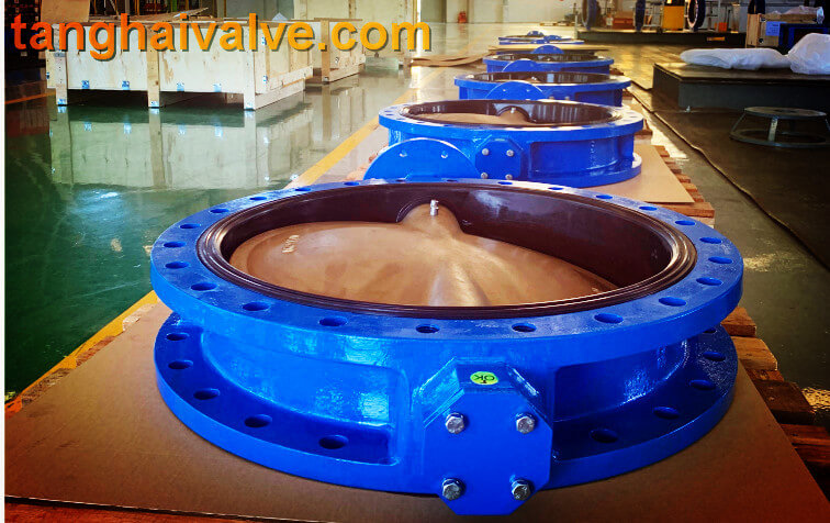
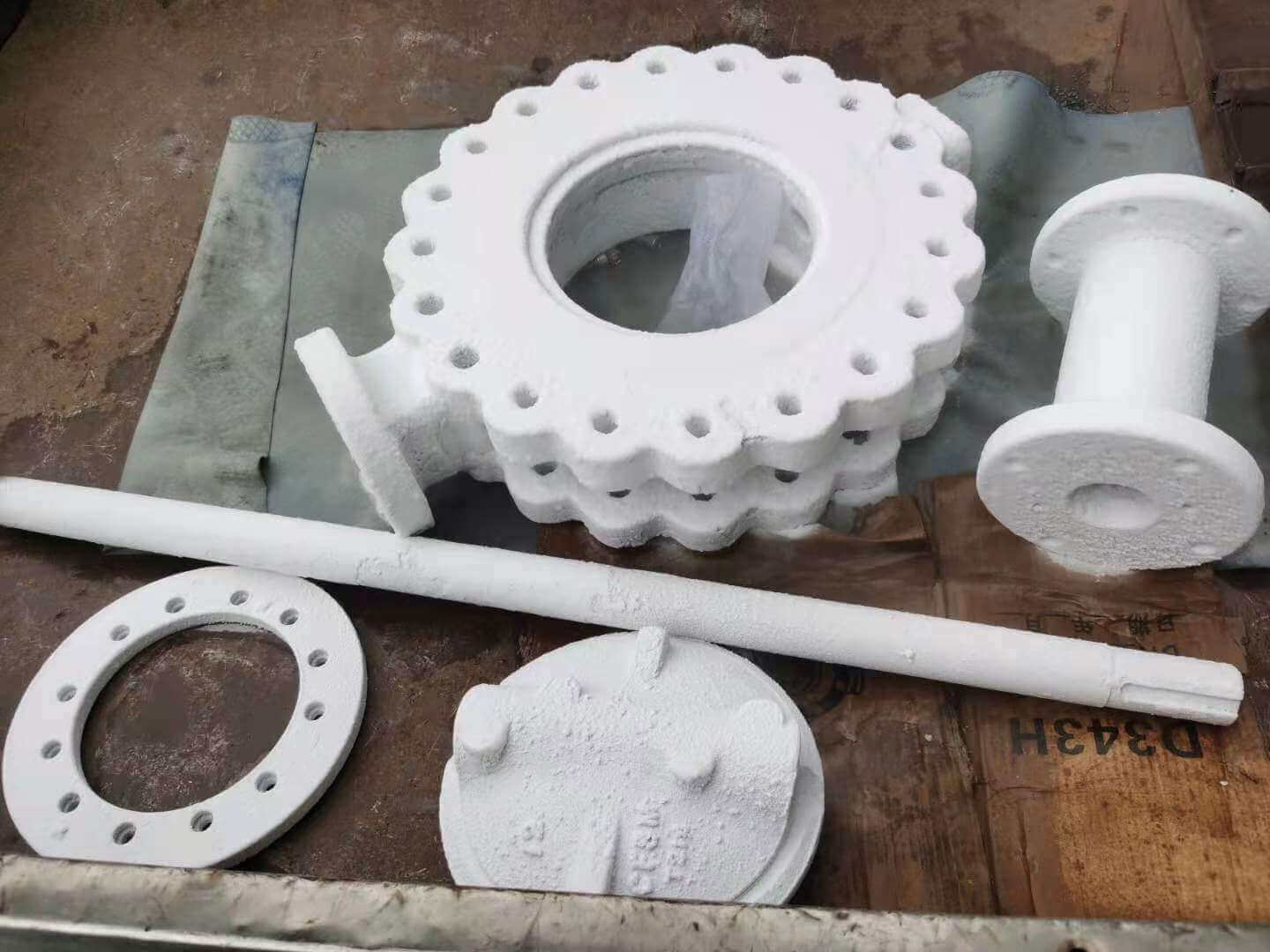
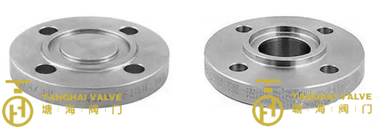
The difference between a fully lined butterfly valve and a half lined butterfly valve:
1. Semi-lined butterfly valve means: the butterfly valve is not lined with rubber, but the place where the butterfly valve is connected to the valve body is lined with rubber;
2. Fully lined butterfly valve means: the butterfly plate of the butterfly valve and the part connected with the valve body are lined with rubber. The difference between rubber-lined butterfly valve, fluorine-lined butterfly valve and plastic-lined butterfly valve: rubber-lined butterfly valve and fluorine-lined butterfly valve are only one kind of plastic-lined butterfly valve.
wafer type butterfly valve (6)
The sealing materials in the rubber-lined butterfly valve are:
Applicable temperature of hard rubber NR: -10℃~85℃,
Applicable temperature of soft rubber BR: -10℃~85℃,
Suitable temperature for butyl rubber IIR: -10℃~120℃,
Applicable temperature of neoprene CR: -10℃~105℃;
The sealing materials in the fluorine-lined butterfly valve are:
Use temperature of polyperfluoroethylene FEP (F46): -85℃~150℃,
Polytetrachloroethylene PTFE (F4) operating temperature: -200℃~180℃,
Polytrifluoroethylene PCTEF (F3) operating temperature: -195℃~120℃,
Polypropylene: RPP operating temperature: -14℃~80℃,
Polyvinyl chloride: rigid) PVC service temperature: 0℃-55℃,
Polyvinylidene chloride PVDF (F2) operating temperature: -70℃~100℃,
Polyolefin: PO Operating temperature: -58℃~80℃.
TH Valve is a professional manufacturer of butterfly valve, gate valve, check valve, globe valve, knife gate valve, ball valve with API, JIS, DIN standard, used in Oil, Gas, Marine industry, Water supply and drainage, fire fighting, shipbuilding, water treatment and other systems, with Nominal Diameter of DN50 to DN1200, NBR/EPDM/VITON, Certificates & Approvals: DNV-GL, Lloyds, DNV, BV, API, ABS, CCS. Standards: EN 593, API609, API6D
Related news/knowledge:
The chemical composition, characteristics and applications of rubbers;
Main application areas of 10 major types of valves;
The difference between American, Germany and China standard valve;
Valve material comparison table-valve pressure-temperature