Butterfly valve use principle and installation instructions
Butterfly valve use principle and installation instructions
The relationship between the opening of the butterfly valve and the flow rate basically changes linearly. If it is used to control flow, its flow characteristics are also closely related to the flow resistance of the piping. For example, two pipelines are installed with the same valve diameter and form, but the pipeline loss coefficient is different, and the flow rate of the valve will also be very different.
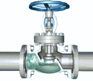
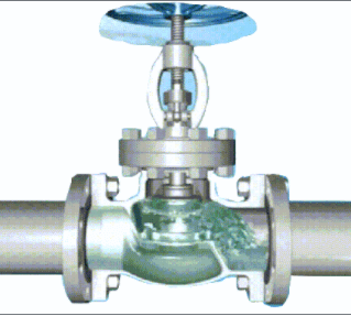
butterfly valve working diagram-3D GIF animated presentation
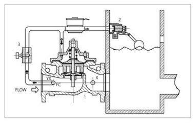
If the valve is in a state with a large throttle range, the back of the valve plate is prone to cavitation, which may damage the valve. Generally, it is used outside 15°. When the butterfly valve is in the middle opening degree, the opening shape formed by the valve body and the front end of the butterfly plate is centered on the valve shaft, and the two sides form different states. Therefore, one side of the valve body and the valve plate form a nozzle-like opening, and the other side is similar to a throttle opening. The nozzle side has a much faster flow rate than the throttle side, and negative pressure will be generated under the throttle side valve. The rubber seal may fall off.
The operating torque of the butterfly valve has different values due to the different opening and closing directions of the valve. The horizontal butterfly valve, especially the large-diameter valve, due to the depth of water, the torque produced by the difference between the upper and lower water heads of the valve shaft cannot be ignored. In addition, when an elbow is installed on the inlet side of the valve, a bias flow is formed and the torque will increase. When the valve is in the middle opening, the operating mechanism needs to be self-locking due to the action of the water flow torque.

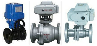
ductile iron, DI, butterfly valve, manufacturer, center line, TH valve
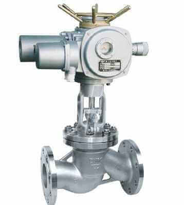
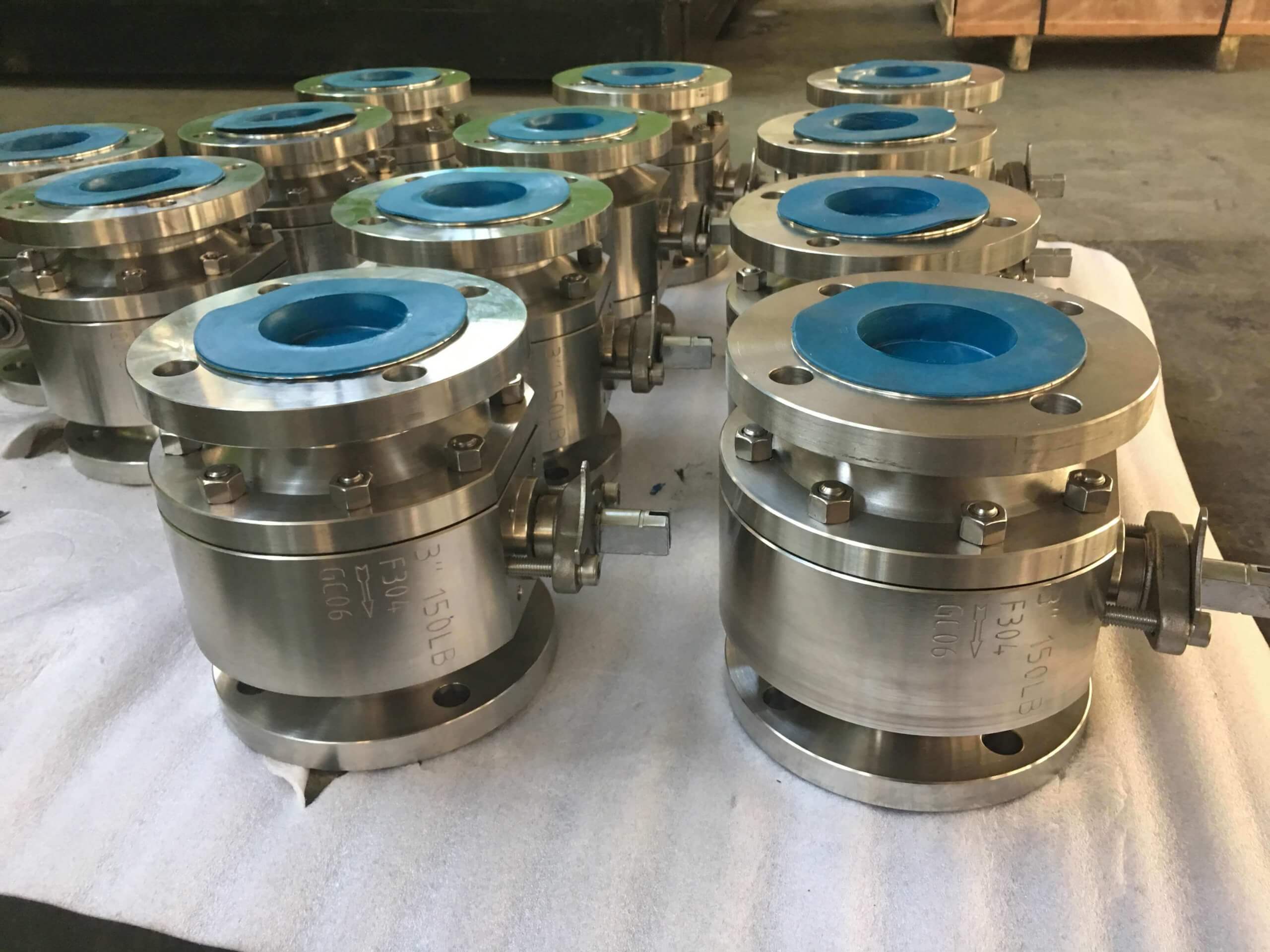
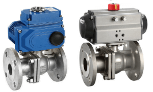
TH Valve is a professional manufacturer of butterfly valve, gate valve, check valve, globe valve, knife gate valve, ball valve with API, JIS, DIN standard, used in Oil, Gas, Marine industry, Water supply and drainage, fire fighting, shipbuilding, water treatment and other systems, with Nominal Diameter of DN50 to DN1200, NBR/EPDM/VITON, Certificates & Approvals: DNV-GL, Lloyds, DNV, BV, API, ABS, CCS. Standards: EN 593, API609, API6D
Related news /products:
Butterfly valve and its Development history – (1);
Working principle diagram of swing check valve;
Valve actuator / actuation -(3)-classifications;
Installation instructions of double eccentric butterfly valve;