Principles of valve selection in the petroleum and chemical industry
Faced with so many valve classifications and such complex various working conditions, to choose the most suitable
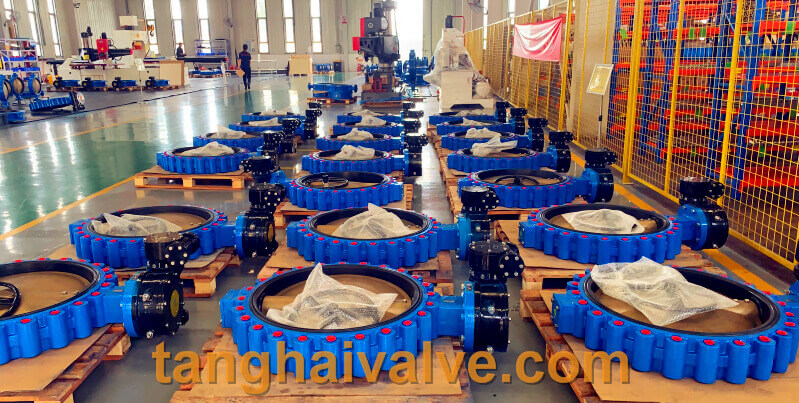
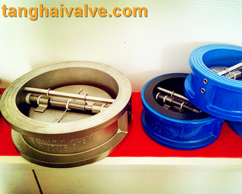
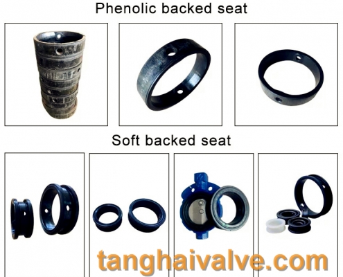
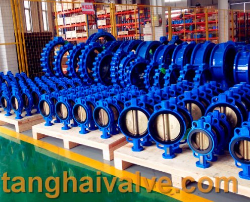
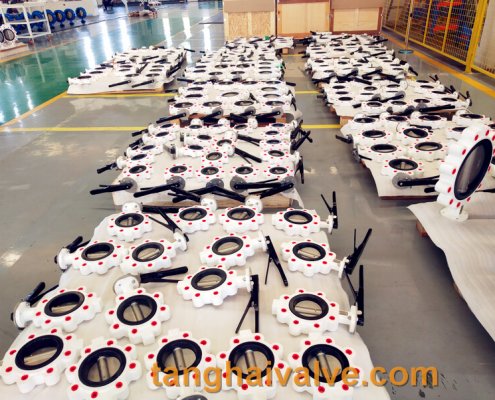
lug type butterfly valve, ductile iron, center lined,
valve product for piping system installation, you should first understand the characteristics of the valve; secondly, you should master the steps and basis for selecting the valve; and then you should follow the choice of oil , The principle of valves used in the chemical industry. The principle of selecting valves in the petroleum and chemical industries: the flow path is a straight-through valve, and its flow resistance is small, and it is usually selected as a shut-off and open medium valve; a valve that is easy to adjust the flow is used as a control flow; a plug valve and a ball valve are more suitable Used for reversing and shunting; the sliding of the closing part along the sealing surface of the valve with wiping effect is most suitable for the medium with suspended particles.
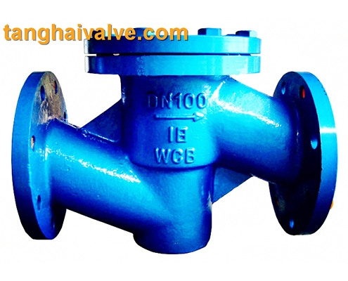
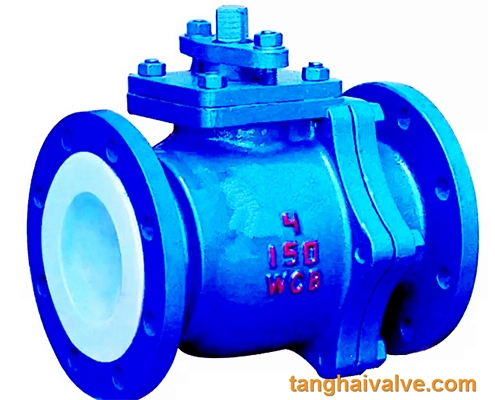
1. Valves for shut-off and open media: The flow channel is a straight-through valve with low flow resistance. It is usually selected as a valve for shut-off and open media. The downward closing valve (stop valve, plunger valve) is less used because of its tortuous flow path and higher flow resistance than other valves. Where higher flow resistance is allowed, a closed valve can be used.

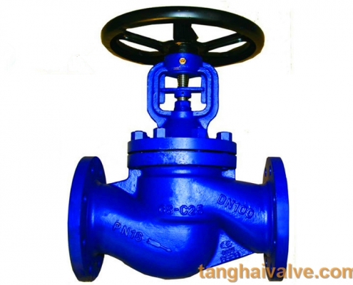
Globe valve (9)
2. Valves used for flow control: Generally, valves that are easy to adjust flow are selected as flow control valves. Downward closing valves (such as globe valves) are suitable for this purpose because the size of its seat is proportional to the stroke of the closing member. Rotary valves (plug valves, butterfly valves, ball valves) and flex-body valves (pinch valves, diaphragm valves) can also be used for throttling control, but they are usually only applicable in a limited range of valve diameters. The gate valve uses a disc-shaped gate to cross-cut the circular valve seat port. It can only control the flow better when it is close to the closed position, so it is usually not used for flow control. 3. Valves for reversing and shunting According to the needs of reversing and shunting, this kind of valve can have three or more channels. Plug valves and ball valves are more suitable for this purpose. Therefore, most of the valves used for reversing and splitting use one of the plug valves and ball valves. However, in some cases, other types of valves can also be used for reversing and shunting as long as two or more valves are properly connected to each other.
4. Valves for medium with suspended particles When there are suspended particles in the medium, it is most suitable for valves with a wiping effect on the sliding of the closing part along the sealing surface. If the back and forth movement of the closing member to the valve seat is vertical, it may hold particles. Therefore, unless the sealing surface material allows particles to be embedded, this valve is only suitable for basic clean media. Ball valves, plug valves, and butterfly valves have a wiping effect on the sealing surface during opening and closing, so they are suitable for use in media with suspended particles.
At present, no matter in the pipeline system of petroleum, chemical industry, or other industries, valve applications, operating frequencies and services are ever-changing. To control or eliminate even low-level leakage, the most important and critical equipment is still valves. The ultimate control of the pipeline is the valve. The service and reliable performance of the valve in various industries are unique.
TH Valve is a professional manufacturer of butterfly valve, gate valve, check valve, globe valve, knife gate valve, ball valve with API, JIS, DIN standard, used in Oil, Gas, Marine industry, Water supply and drainage, fire fighting, shipbuilding, water treatment and other systems, with Nominal Diameter of DN50 to DN1200, NBR/EPDM/VITON, Certificates & Approvals: DNV-GL, Lloyds, DNV, BV, API, ABS, CCS. Standards: EN 593, API609, API6D
Related news /knowledge:
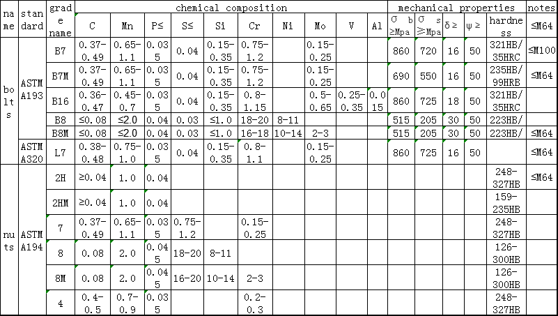
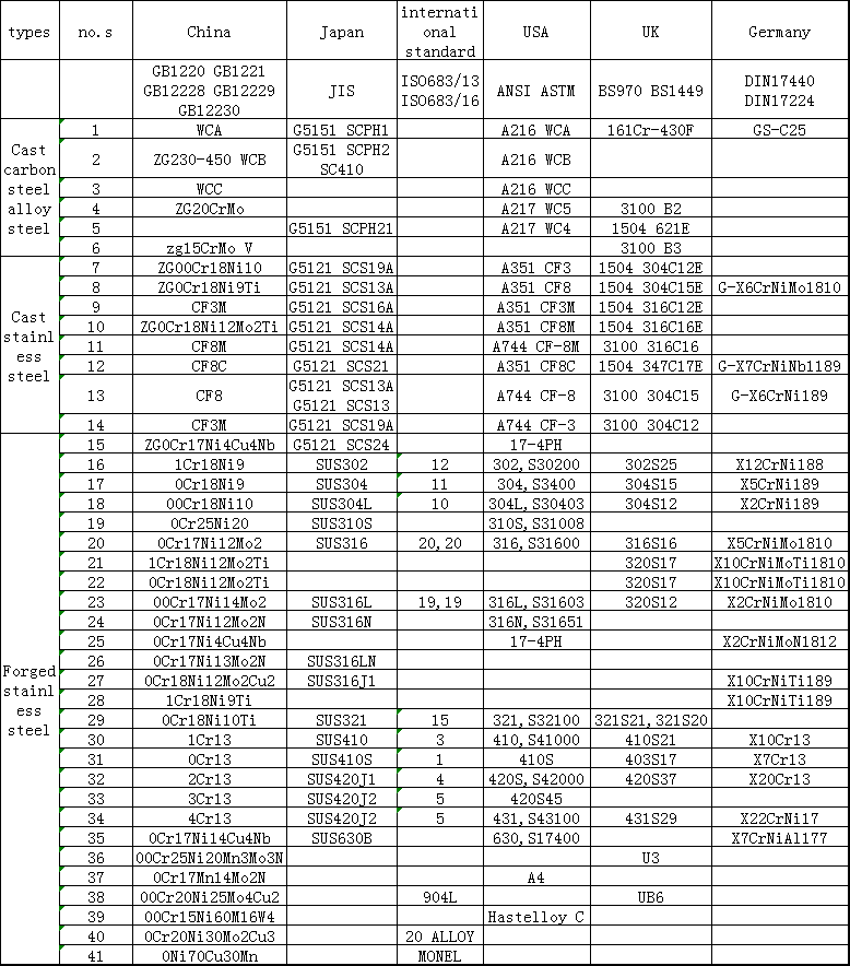
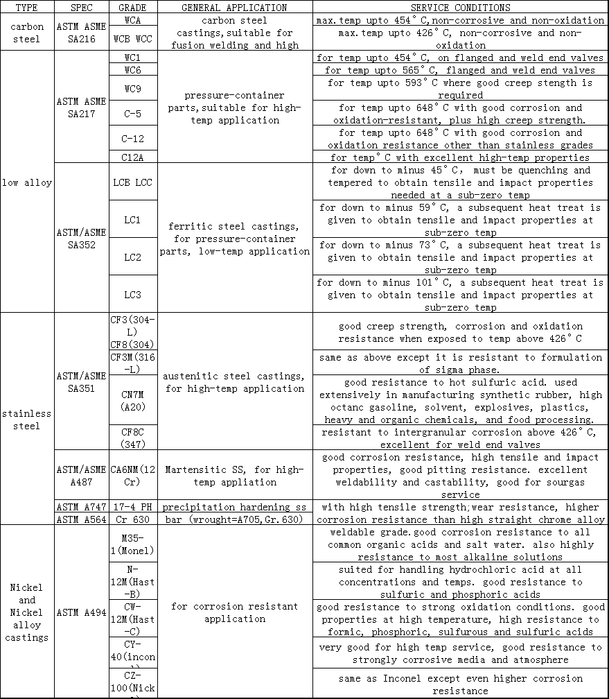
Stainless steel valve material parameters and specific applications;
Notes on selection and installation of butterfly valve;
Types and selection of electric valves;
Pneumatic butterfly valve working principle diagram.