Tag Archive for: flange

Posts

Butterfly Valve of Marine Valves(tanghai valve)

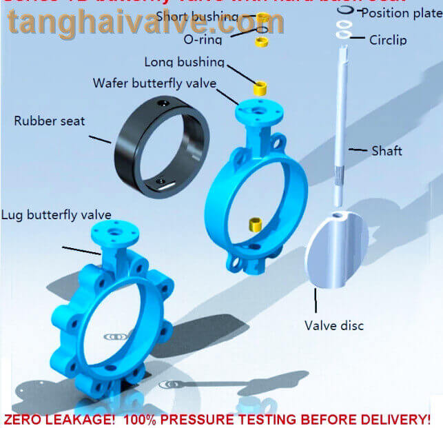
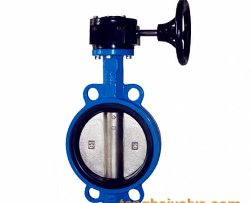
A butterfly valve used in marine applications, often referred to simply as a marine butterfly valve, is a critical component in ship systems for controlling the flow of fluids such as water, fuel, and various other liquids.

Here’s an overview Features: 

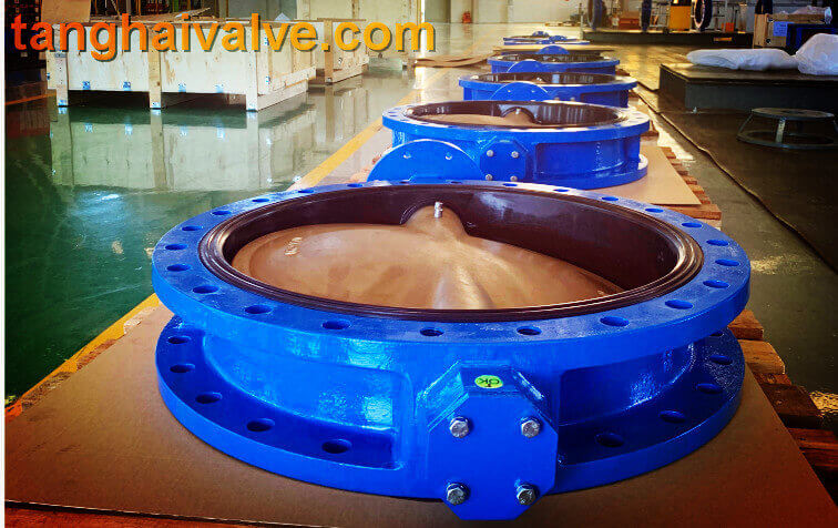
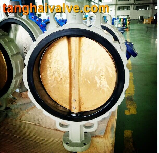
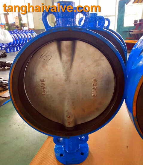
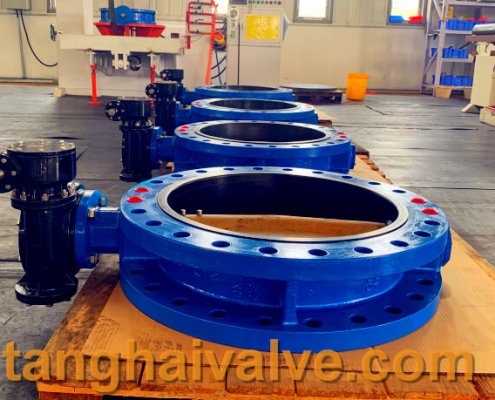
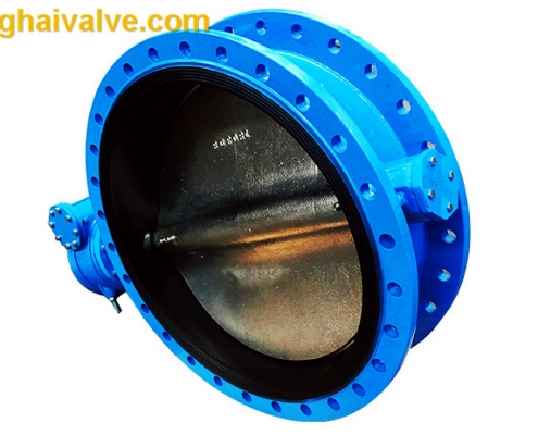
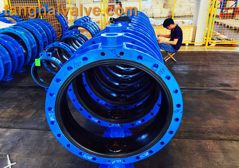
  1. corrosion Resistance: Marine environments expose valves to corrosive elements like saltwater. Hence, marine butterfly valves are typically made from materials such as bronze, stainless steel, or other corrosion-resistant alloys.
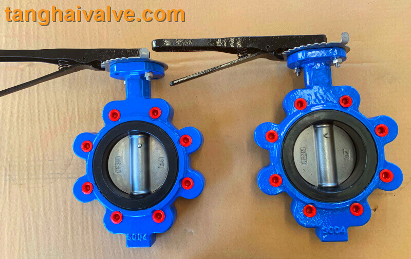
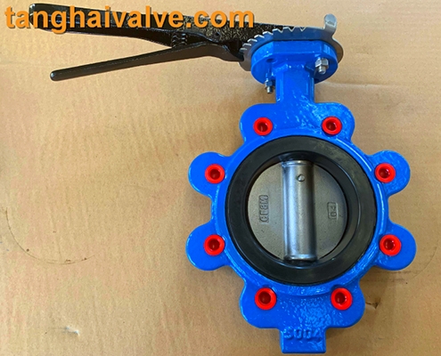
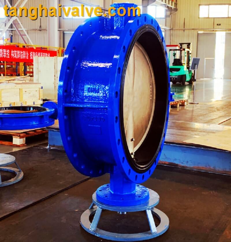
  2. Compact Design: Space is often limited aboard ships, so marine butterfly valves are designed to be compact and lightweight while still providing efficient flow control.
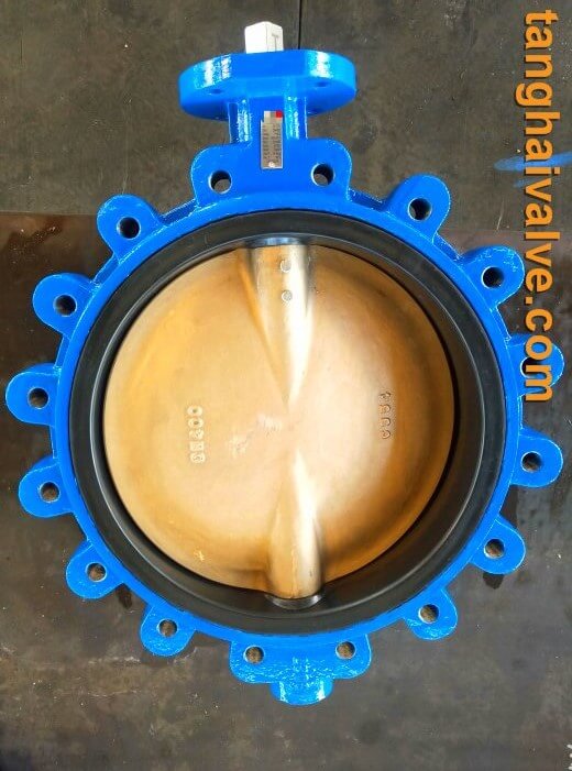
  3. Resilient Seating: Many marine butterfly valves feature resilient seating made of materials like EPDM or NBR, which offer excellent sealing properties and resistance to wear, corrosion, and chemicals.
  4. Bidirectional Sealing: Butterfly valves are inherently bidirectional, meaning they can effectively seal flow in both directions, allowing flexibility in installation and operation.
  5. Manual or Actuated Operation: Marine butterfly valves can be operated manually using a hand lever or wheel, or they can be equipped with pneumatic, electric, or hydraulic actuators for remote operation and automation.

Selection Considerations:

  1. Size and Pressure Rating: Choose a valve size and pressure rating suitable for the intended application and system requirements aboard the ship.
  2. Material Compatibility: Select materials compatible with the fluids being handled and resistant to corrosion in the marine environment.
  3. Sealing Material: Consider the type of sealing material based on temperature, pressure, and fluid properties to ensure reliable performance and longevity.
  4. Operation Type: Determine whether manual or actuated operation is preferable based on accessibility, control requirements, and automation needs.
  5. Compliance and Certification**: Ensure the selected valve meets relevant industry standards and certifications for marine applications, such as those from classification societies like DNV, ABS, or Lloyd’s Register.

Usage:

  1. Installation: Install the marine butterfly valve correctly according to manufacturer specifications, ensuring proper alignment, bolt torquing, and gasket sealing between flanges.
  2. Operation: Operate the valve using the designated controls, whether manual or actuated, following established procedures for opening, closing, and adjusting flow rates as needed.
  3. Maintenance: Implement a regular maintenance schedule to inspect, clean, lubricate, and replace components as necessary to ensure optimal performance and reliability.
  4. Monitoring: Periodically monitor the valve’s operation and condition for signs of leakage, wear, or malfunction, and take corrective action as required to prevent downtime or safety hazards.
  5. Emergency Response: Establish protocols for responding to valve failures, leaks, or other emergencies, including shutdown procedures, isolation measures, and contingency plans to mitigate risks and minimize disruptions.         By considering these factors and adhering to best practices for selection, installation, operation, and maintenance, marine butterfly valves can effectively control flow and contribute to the safe and efficient operation of ship systems.

Marine Butterfly Valves are Used to Close or Open the Medium in the Ballistic Channel (Tanghai Valve)

Valve selection of a single variety of valve goods, marine valve speech is inconsistent, partly by use (such as chemical, alcohol, power station, etc.), partly by medium (such as water vapor, atmosphere valve, etc.), partly by material (such as pig iron valve, cast steel valves, forged steel valves, etc.), partly by the way of connection (such as fingerprints, flange valves, etc.), and partly by the measurement (such as high-temperature valves, low-temperature valves, etc.). The following is a list of the most common types of pressure reducing valves for marine use.

Marine pressure reducing valve – used to actively elevate the ballistic and facilities within the medium pressure. Marine pressure-reducing valve medium through the valve flap gap, marine pressure-reducing valve occurs barrier formation pressure loss, to reach the means of pressure reduction. Trap – used to steam ballistic actively remove condensate, to prevent the loss of steam or leakage. Marine butterfly valve is used to close or open the ballistic medium. Can also be used for conditioning. Insurance valve – used in boilers, ware facilities and ballistic, when the media pressure stumbles over the rule value, can actively remove the excess media pressure, to protect the consumption of operational insurance.

In the power station valves can master the boiler and steam engine operation; in alcohol, chemical consumption, the valve also plays a role in mastering the whole consumer facilities and process line of the abnormal operation. In other units are also like that. In spite of this, valves are often ignored by the crowd compared with other goods. Similarly: when installing tools and facilities, people often focus on the main tools and facilities range. Therefore, for the valve selection, installation, use and so on need to be careful.

TH Valve is a professional manufacturer of butterfly valve, gate valve, check
valve, globe valve, knife gate valve, ball valve with API, JIS, DIN standard, used in Oil,
Gas, Marine industry, Water supply and drainage, fire fighting, shipbuilding, water
treatment and other systems, with Nominal Diameter of DN50 to DN1200,
NBR/EPDM/VITON, Certificates & Approvals: DNV-GL, Lloyds, DNV, BV, API, ABS, CCS.
Standards: EN 593, API609, API6D

Marine butterfly valve–Application of Marine Butterfly Valves

Marine butterfly valve is a kind of valve used to control or cut off fluid in liquid or gas flow pipeline on board. The characteristics of marine butterfly valves are simple structure, light weight, convenient operation, and good safety in use. Below, we will introduce marine butterfly valves in several aspects.

 1 Application of Marine Butterfly Valves

Marine butterfly valves are widely used for regulating and cutting off liquid flow and gas in various oil tankers, Chemical tanker, natural gas tankers, liquefied gas tankers and rescue ships. And it can also be applied in other equipment and pipelines, such as petrochemical, energy, metallurgy, power, water treatment and other fields.

 2 Structure of butterfly valve

Marine butterfly valves generally adopt a circular flat surface on the outside, and are composed of bent plates and closed gaskets on the inside. The valve stem and valve disc are rigidly connected through suitable mechanical connections, and the valve disc is configured into the pipeline to control the flow rate by relying on the flow force itself.

 3 Characteristics of Marine Butterfly Valves

 1Simple structure, small size, light weight, and low flow resistance.

2Quick opening and closing, easy to operate, and reduces fluid switching time.

 3 Corrosion resistance, reliable sealing, and good leak prevention effect.

 4Long service life and simple maintenance.

 5 Its special structural design ensures that it still retains the advantages of no combustion, leak prevention, and fire resistance under low pressure, small diameter, and critical conditions.

4 Selection Method of Marine Butterfly Valves

When selecting a marine butterfly valve, it is necessary to consider parameters such as the nominal diameter, pressure rating, mode of action, and medium temperature of the butterfly valve. It is best to make a choice based on specific conditions.

It is necessary to consider the operating temperature and medium characteristics, and appropriate valve diameters and shear forces should be designed based on the flow speed of the medium, and appropriate materials or sealing forms should be selected.

5 How to Use and Maintain Marine Butterfly Valves

When using marine butterfly valves, attention should be paid to the installation direction and the position of the blocking plate to ensure that the valve is straight and to avoid tilting damage and leakage during operation.

For the maintenance and upkeep of marine butterfly valves, it is necessary to conduct timely inspections, regularly lubricate the valve and its surrounding components, and clean the operating bearings, gaskets, sealing surfaces, and bearings. Special attention should be paid to key areas.

Finally, we need to regularly conduct statistics and analysis on the usage of marine butterfly valves, compare them with other similar equipment, identify problems in the operation of butterfly valves, and promptly handle them. Only by doing well in daily maintenance and paying sufficient attention can the normal operation of butterfly valves be guaranteed and their service life be extended.

Finally, we need to regularly conduct statistics and analysis on the usage of marine butterfly valves, compare them with other similar equipment, identify problems in the operation of butterfly valves, and promptly handle them. Only by doing well in daily maintenance and paying sufficient attention can the normal operation of butterfly valves be guaranteed and their service life be extended.
Tianjin Tanghai Valve Co., Ltd. is a professional marine valve manufacturer, including butterfly valve, check valve, gate /Knife gate valve. We have certificates: CE, ISO, BV, DNV foundry andproducts approval. Now we have our own independent R & D, manufacturing, assembly and warehousing workshops; we have professional pre-sale and after-sale technical support and perfect services.Below is our wafer butterfly valve of marine valves,if you need to check more information,please click here:https://www.tanghaivalve.com/wafer-type-butterfly-valve-th-btv-aw/.Please contact us if you need more support, please contact us freely: info@tanghaivalve.com.We are committed to “Build a top valve enterprise; Be a reliable partner!”
Friends from all over the world are welcome to visit us for evaluation, guidance, and orders!

7 types of flange sealing surface: FF, RF, M, FM, T, G, RTJ

Flanged butterfly valve has a flange on the valve, and bolts are used to connect the flanges at both ends of the valve to the pipe flange. Do you know all the 7 types of flange sealing surfaces? FF, RF, MF, M, T, G, RTJ
The flange sealing surface basically has:

Full plane: FF
Raised face: RF
Concave/female: FM
Convex/Male: M
Tenon: T
Groove surface: G
Ring connection surface RTJ (RJ)  types, according to the different working conditions, medium, pressure, specifications, temperature, etc., so the selected types are not the same. Let’s get to know the types of these flange sealing surfaces together!
FF-full plane:
Flat Face Full Face type sealing surface is completely flat, suitable for occasions where the pressure is not high and the medium is non-toxic.

flange FF

flange FF 

RF-raised face:
The Raised Face type of sealing surface is the most widely used among several types, and the most commonly used one. The international standards, European system and domestic standards are all fixed heights, but in the American standard flange, it should be noted that the height of high pressure will increase the sealing surface. There are also many types of gaskets used. Gaskets suitable for raised face sealing surface flanges include various non-metallic flat gaskets, coated gaskets; metal-wrapped gaskets; spiral wound gaskets (including outer ring or inner and outer ring).

flange RF

flange RF

Convex/Male: M
Concave /female: FM
The two types of sealing surfaces, Male Face and Female Face, are a pair, one female and one male. They must be used together. They are easy to align and prevent the gasket from being extruded. Suitable for occasions with higher pressure.
The suitable sealing gaskets for the concave-convex sealing surface include: various non-metallic flat gaskets and coated gaskets; metal-clad gaskets; basic type or winding stopper with inner ring, etc.
T-tenon
G-groove surface
Tongue Face and Groove Face are similar to the concave-convex surface. They are also a male and female matched sealing surface type, and they are also used in pairs. The gasket is located in the annular groove and is restricted by the metal walls on both sides. It can prevent the gasket from being compressed and deformed and squeezed into the pipeline. Since the gasket is not in direct contact with the fluid medium in the pipe, it is less eroded or corroded by the fluid medium, so it can be used for high pressure, flammable, explosive, and toxic mediums that require strict sealing. This kind of sealing surface gasket has good installation and neutrality, but it is difficult to process the sealing surface. It is easy to damage the sealing surface when replacing the gasket, and the flange must be separated in the axial direction during installation and disassembly. Therefore, consideration should be given to the pipeline design. It is possible to separate the flange in the axial direction.
Suitable gaskets for the sealing surface of the tongue and groove surface include: various metal and non-metal flat gaskets, metal-clad gaskets and basic spiral wound gaskets.

flange TG-

flange TG-

RTJ(RJ)-Ring connection surface
The flange of the Ring Joint Face seal is also a narrow-face flange, and an annular trapezoidal groove is opened on the flange surface as the flange sealing surface, which is the same as the tongue-and-groove flange. The flange must be separated in the axial direction during installation and disassembly. Therefore, the possibility of separating the flange in the axial direction should be considered in the pipeline design.
The sealing surface is specially designed to cooperate with solid metal gaskets processed into octagonal or elliptical shapes from metal materials to achieve a sealed connection. Since the metal ring gasket can be based on the inherent characteristics of various metals, the sealing performance of this sealing surface is good, and the installation requirements are not too strict. It is suitable for high temperature and high pressure working conditions, but the processing accuracy of the sealing surface is relatively high. (According to the Pipe Fittings, Pumps and Valves Alliance)

flange-RTJ-RJ-

flange-RTJ-RJ-

flange-RTJ-RJ-02

flange-RTJ-RJ-02

What is butt welding? (1)

Butt resistance welding (hereinafter referred to as butt welding) is a type of resistance welding method that uses resistance heat to weld two workpieces along the entire end surface at the same time. Butt welding has high

welding

welding

productivity and easy automation, so it is widely used.
Application of butt welding:
Butt welding has high productivity and easy automation, so it is widely used. Its application range can be summarized as follows:
(1) The length of the work piece, such as the butt welding of strip steel, profile, wire, steel bar, rail, boiler steel pipe, oil and natural gas transportation pipeline.
(2) Butt welding of annular workpieces, such as car rims and bicycles, motorcycle rims, butt welding of various chain links, etc.
(3) Assembling welding of components The simple rolling, forging, stamping or machining parts are butt-welded into complex parts to reduce costs. For example, butt welding of automobile steering shaft shell and rear axle housing, butt welding of various connecting rods and tie rods, and butt welding of special parts.
(4) Butt welding of dissimilar metals can save precious metals and improve product performance. For example, the butt welding of the working part of the tool (high-speed steel) and the tail (medium carbon steel), the butt welding of the head (heat-resistant steel) and the tail (structural steel) of the exhaust valve of an internal combustion engine, the butt welding of aluminum and copper conductive joints, etc. .
Classification of butt welding:
Butt welding is divided into resistance butt welding and flash butt welding.
Resistance butt welding
Resistance butt welding is a method in which the end faces of the two workpieces are always pressed tightly, heated to a plastic state by resistance heat, and then upset pressure is quickly applied (or no upset pressure is applied and only the pressure during welding is maintained) to complete the welding.
One, resistance and heating of resistance butt welding
The resistance distribution during butt welding is shown in the figure. The total resistance can be expressed by the following formula:
R=2Rω+RC+2Reω
where Rω-the internal resistance of the conductive part of a workpiece (Ω);
Rc–the contact resistance between two workpieces (Ω);
Rω–The contact resistance between the workpiece and the electrode (Ω);
The contact resistance between the workpiece and the electrode is usually ignored due to its small resistance and far from the joint surface.
The internal resistance of the workpiece is proportional to the resistivity ρ of the welded metal and the length l0 of the workpiece extending from the electrode, and inversely proportional to the cross-sectional area s of the workpiece.
Same as spot welding, the contact resistance of resistance butt welding depends on the surface condition, temperature and pressure of the contact surface. When the contact resistance has obvious oxides or other stolen goods, the contact resistance is large. The increase in temperature or pressure will reduce the contact resistance due to the increase in the actual contact area. At the beginning of welding, the current density at the contact point is very large; after the end surface temperature rises rapidly, the contact resistance decreases sharply. When heated to a certain temperature (steel 600 degrees, aluminum alloy 350 degrees), the contact resistance disappears completely.
Like spot welding, the heat source during butt welding is also the resistance heat generated by the resistance of the welding zone. In resistance butt welding, the contact resistance exists for a very short time, and the heat generated is less than 10-15% of the total heat. But because this part of the heat is generated in a very narrow area near the contact surface. Therefore, the temperature in this area will increase rapidly, and the internal resistance will increase rapidly. Even if the contact resistance disappears completely, the heat generation intensity in this area is still higher than other places.
The harder the welding rod used (that is, the larger the current and the shorter the energization time), the smaller the pressing force of the workpiece, and the more obvious the influence of contact resistance on heating.

Raised face flange and concave and convex face flange

Flange is used for the connection between two devices. The abbreviation refers to the form of the sealing surface. There are holes on it. The two flanges are connected by bolts. It is generally used for The mutual connection between

flanges

flanges

the shaft and the shaft is also used for the connection between the pipe ends; it is a detachable connection of a set of combined sealing structures that are connected by flanges, gaskets and bolts. The thickness of flanges with different pressures is different, and their use forms are also different.

Commonly used butterfly valves include wafer butterfly valves and flange butterfly valves. Wafer type butterfly valve uses double-head bolts to connect the valve between two pipe flanges. Flange type butterfly valve has flanges on the valve, and the two ends of the valve are flanged to the pipe flanges with bolts.
For the most common raised face flanges and concave and convex face flanges, in the flange connection, the raised face flange needs to be matched with the concave face flange, commonly known as one male and one female, and the raised face flange should be matched with the raised face flange. Generally speaking, raised face flanges should also be a kind of flat flanges, code-named RF, and the RF face can only be linked with the RF face. The code name of the raised face flange is M, and the M face flange needs to be connected with the FM face. One is female FM (Female Male), and the other is male M (Male). The pressure on the M/FM side is better than that on the RF side. Raised face flanges and raised face flanges are used in pairs, and the code name is RF. The comparison chart of the two is as follows:

RF, MFM flanges

RF, MFM flanges

The angle between the sealing surface of the raised face flange and the flange bolt connection surface is 45°, and the sealing surface of the concave and convex flange and the flange bolt connection surface are 90° angle, that is, the two sides are perpendicular .

Raised face flanges are more commonly used in the market, and generally there is no problem below 2.5MPa. Concave-convex flanges are more expensive and have better sealing effect, so the applicable pressure level is higher. When designing, it is more troublesome. For example, when you mention the equipment condition diagram, you must indicate what type of method it is. Lan, and then when the statistics take over the material, it is another matching flange.

TH Valve is a professional manufacturer of butterfly valvegate valvecheck valveglobe valveknife gate valve, ball valve with API, JIS, DIN standard, used in Oil, Gas, Marine industry, Water supply and drainage, fire fighting, shipbuilding, water treatment and other systems, with Nominal Diameter of DN50 to DN1200, NBR/EPDM/VITON, Certificates & Approvals: DNV-GL, Lloyds, DNV, BV, API, ABS, CCS. Standards: EN 593, API609, API6D

Related news /knowledge:
7 types of flange sealing surface: FF, RF, M, FM, T, G, RTJ;
What is butt welding? (2);
What is butt welding? (5)- flash butt welding;
Features and structure drawings of flange butterfly valve

The main classification method of butterfly valve (2)

According to the connection method, the butterfly valve can be devided into four or five types:

1. Wafer type butterfly valve

Wafer type butterfly valve with worm gear

Wafer type butterfly valve with worm gear

The butterfly plate of the wafer butterfly valve is installed in the diameter direction of the pipeline. The valve is fully open.
Wafer type butterfly valve has simple structure, small volume and light weight. There are two types of butterfly valve: elastic seal and metal seal. Elastic sealing valve, the sealing ring can be embedded on the valve body or attached to the periphery of the butterfly plate.

2. Lug butterfly valve

2 lug-type-butterfly-vlave-6

2 lug-type-butterfly-vlave-6

The butterfly plate of the lug butterfly valve is installed in the diameter direction of the pipeline. The butterfly plate rotates around the valve shaft, and the rotation angle is between 0°-90°. When it rotates to 90°, the valve is fully open.

3. Flanged butterfly valve

U-type flange butterfly valve, ductile iron, DI, center line,

U-type flange butterfly valve, ductile iron, DI, center line,

Double flange butterfly valve (4)

Double flange butterfly valve (4)

The flanged butterfly valve has a vertical plate structure, and the valve stem is an integral type. Metal hard seal, valve sealing ring
It is a composite structure of flexible graphite plate and stainless steel plate, which is installed on the valve body, and the sealing surface of the butterfly plate is welded with stainless steel. The sealing ring of the soft seal valve is made of nitrile rubber, EPDM or VITON, and is installed on the butterfly plate. The sealing seat of the centerline sealed flange butterfly valve is directly fusion bonded on the valve body.
Flanged butterfly valves are divided into U-shaped butterfly valves and double-flanged butterfly valves according to the length of the structure. The U-type butterfly valve has a relatively short face to face structure, which reduces the weight of the valve body and saves space for use.

4. Welded butterfly valve
Welded butterfly valve is a non-hermetic butterfly valve, widely used in the construction materials, metallurgy, mining, electric power and other production processes, the medium temperature ≤300 ℃, the nominal pressure is 0.1Mpa pipeline, used to communicate, open or close or adjust the medium volume.

The electric regulating butterfly valve belongs to a variety of electric valves and electric regulating valves. The main connection methods are: flange type and wafer type, which are important execution units in the field of industrial automation control. Two major analysis points for the installation points of the electric adjustment butterfly valve: the installation position, height, and inlet and outlet directions must meet the design requirements. Note that the direction of the medium flow should be consistent with the direction of the arrow marked on the valve body, and the connection should be firm and tight. Before installing the electric butterfly valve, a visual inspection must be carried out. The nameplate of the valve should comply with the provisions of the current national standard “General Valve Mark” GB12220. For valves with a working pressure greater than 1.0 MPa and acting as a shut-off on the main pipe, a strength and tight performance test should be carried out before installation. Use only after passing the test. During the strength test, the test pressure is 1.5 times the nominal pressure, the duration is not less than 5min, and the valve housing and packing should be leak-free. The electric adjustable butterfly valve can be divided into offset plate type, vertical plate type, inclined plate type and lever type according to the structural form; according to the sealing form, it can be divided into two types: soft seal type and hard seal type; soft seal type generally adopts rubber ring seal, hard seal type Usually a metal ring seal is used.

TH Valve is a professional manufacturer of butterfly valvegate valvecheck valveglobe valveknife gate valve, ball valve with API, JIS, DIN standard, used in Oil, Gas, Marine industry, Water supply and drainage, fire fighting, shipbuilding, water treatment and other systems, with Nominal Diameter of DN50 to DN1200, NBR/EPDM/VITON, Certificates & Approvals: DNV-GL, Lloyds, DNV, BV, API, ABS, CCS. Standards: EN 593, API609, API6D

related news: What is a wafer type butterfly valve; The structure and application fields of the lug type butterfly valve