Tag Archive for: actuator

Posts

Valve actuator / actuation -(4)-angle stroke valve actuator application

Angle stroke valve actuator application products:
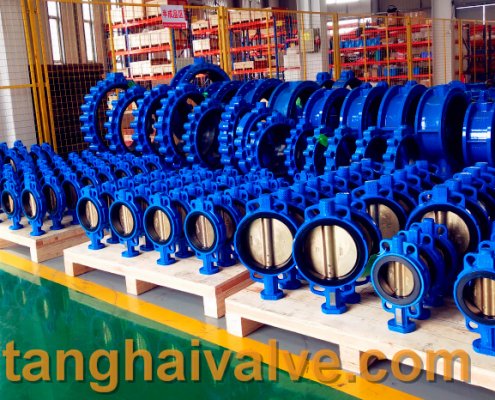
1. Butterfly valve:
The baffle of the butterfly valve controls the flow of fluid with the rotation of the shaft. It is composed of valve body, baffle, baffle shaft and shaft seal. Its simple structure, small size, light weight, low cost and large flow capacity are especially suitable for occasions with low pressure difference, large diameter, large flow gas and fluid with su

ductile iron, DI, butterfly valve, manufacturer, center line, TH valve

ductile iron, DI, butterfly valve, manufacturer, center line, TH valve

spended solids, but the leakage is large. Its flow characteristics are achieved at the corners. The front and equal percentage characteristics are similar, but the work will be unstable and the characteristics will not be good in the future; use in the corner range. Butterfly valves are not only widely used in general industries such as petroleum, gas, chemical, and water treatment, but also used in cooling water systems of thermal power stations.
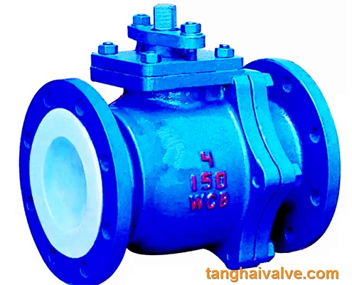
2. Ball valve:
The ball valve is defined in the standard GB/T21465-2008 “Valve Terminology” as a valve in which the opening and

closing part (sphere) is driven by the valve stem and rotates around the axis of the valve stem. The ball valve has a 90-degree rotation. The cock body It is a sphere with a circular through hole or channel passing through its axis. It is mainly used to cut off or connect the medium in the pipeline, and can also be used for fluid adjustment and control. Among them, the hard-sealed V-shaped ball valve has a strong shear between the V-shaped core and the metal seat of the hard alloy. Shearing force is especially suitable for media containing fibers and tiny solid particles. The multi-way ball valve can not only flexibly control the confluence, divergence, and flow direction switching of the

14 ball-valve-6

14 ball-valve-6

medium in the pipeline, but also close any channel and connect the other two channels. This type of valve should generally be installed horizontally in the pipeline. Ball valve classification: pneumatic ball valve, electric ball valve, manual ball valve. The ball valve can be closed tightly with only a 90-degree rotation and a small torque. The ball valve is most suitable for use as a switch and shut-off valve, V-shaped ball valve. In the developed western countries, the use of ball valves is increasing year by year. In our country, ball valves are widely used in petroleum refining, long-distance pipelines, chemicals, papermaking, pharmaceuticals, water conservancy, electric power, municipal administration, steel and other industries. Occupy a pivotal position in the national economy.

3. Cam flex valve:

Cam flex valve, also known as eccentric rotary valve, is also a new-type regulating valve. The center line of the spherical valve core deviates from the center of the rotating shaft, and the rotating shaft drives the valve core to rotate eccentrically, so that the valve core enters the valve seat forward and downward.

The eccentric rotary valve has the advantages of small size, light weight, reliable use, convenient maintenance, strong versatility, and low fluid resistance. It is suitable for occasions with high viscosity and has good performance in lime, mud and other fluids.

TH Valve is a professional manufacturer of butterfly valvegate valvecheck valveglobe valveknife gate valve, ball valve with API, JIS, DIN standard, used in Oil, Gas, Marine industry, Water supply and drainage, fire fighting, shipbuilding, water treatment and other systems, with Nominal Diameter of DN50 to DN1200, NBR/EPDM/VITON, Certificates & Approvals: DNV-GL, Lloyds, DNV, BV, API, ABS, CCS. Standards: EN 593, API609, API6D

Related news/knowledge:

Types and working principles of electric valves;
Pneumatic ball valve principle, structure and working principle;
The working principle of butterfly valve (picture);
Characteristics and working principle of electric globe valve

Valve actuator / actuation -(3)-classifications

Double acting valve actuator:
The selection of double-acting actuators takes DA series pneumatic actuators as an example. The output torque of

Pneumatic actuator (2)

Pneumatic actuator (2)

the gear-and-pinion actuator is the piston pressure (supplied by the air source pressure) multiplied by the pitch circle radius (arm). And the friction resistance is small and the efficiency is high. The output torque is linear when rotating clockwise and counterclockwise. Under normal operating conditions, the recommended safety factor for double-acting actuators is 25-50%

Single-acting valve actuator:
The selection of single-acting actuator takes the SR series pneumatic actuator as an example. In the application of spring return, the output torque is obtained during two different operations. According to the stroke position, each operation produces two different torque values. The output torque of the spring-return actuator is obtained by multiplying the force (air pressure or spring force) by the force arm. The first situation: the output torque is obtained by air pressure entering the central cavity to compress the spring, which is called “air stroke output torque”. In this case, the air source pressure forces the piston to turn from 0 degrees to 90 degrees. Due to the reaction force generated by the compression of the spring, the torque gradually decreases from the maximum value

hydraulic actuator for marine valve

hydraulic actuator for marine valve

at the starting point to the second condition: the output torque is the spring recovery when the middle cavity loses air. The force acting on the piston is called “spring stroke output torque”. In this case, due to the extension of the spring, the output torque gradually decreases from 90 degrees to 0 degrees. As mentioned above, the single-acting actuator is based on two It is designed on the basis of generating a balance torque under this condition.

Linear valve actuator:
1. Through single seat valve

The so-called single seat means that there is only one valve core and one valve seat in the valve body. Its characteristics are simple structure, small leakage (even completely cut off) and small allowable pressure difference. Therefore, it is suitable for occasions requiring clean media with small leakage and small working pressure difference. Special attention should be paid to the allowable pressure difference in the application to prevent the valve from closing.

2. Straight through double seat valve

There are two valve cores and valve seats in the valve body of the straight-through double-seat regulating valve. Compared with the single seat valve of the same caliber, its flow capacity is about 20% to 25% larger. Because the force of the fluid on the upper and lower valve cores can cancel each other, but the upper and lower valve cores are not easy to close at the same time, the double seat valve has the characteristics of large allowable pressure difference and large leakage. Therefore, it is suitable for clean media where the pressure difference between the two ends of the valve is large and the leakage requirement is not high. It is not suitable for high viscosity and fiber-containing occasions.

3. Angle valve

The valve body of the angle control valve is right-angled, its flow path is simple, and the service force is small. It is suitable for the control of high pressure difference, high viscosity, suspended solids and granular materials. Generally used for bottom inlet and side outlet, this kind of control valve has better stability. In high pressure situations, in order to prolong the service life of the spool, the side inlet and the bottom outlet can be used, but oscillation is prone to occur in small openings.

Valve actuator / actuation -(2)-classification and working principle

Classification of valve actuators:
(1) According to the driving energy used, the actuator is divided into three types: pneumatic, electric and hydraulic actuators.
(2) According to the form of output displacement, the actuator has two types: angle type and linear type.

Pneumatic actuator (2)

Pneumatic actuator (2)

(3) According to the law of action, actuators can be divided into three types: switch type, integral type and proportional type.
(4) According to the input control signal, the actuator can be divided into several types, such as air pressure signal, direct current signal, electric contact on-off signal, pulse signal, etc.

The working principle of valve actuator:
In the gear stage, the engine speed can be transmitted to the output rod through two sets of gears. The main reducer is completed by planetary gears, and the auxiliary reducer is realized by worm gears, which are fixed in the center by a set of tight springs. In the event of an overload, that is, when the output rod exceeds the set torque of the spring, the central worm gear will undergo axial displacement, and the switches and

electric actuator for valve

electric actuator for valve

signal devices will be fine-tuned to provide protection for the system. The output rod is coupled with the worm gear when the engine is working, and is coupled with the hand wheel when it is manually operated, under the action of the coupling operated by the external change control lever. When the engine is not working, the motor drive can be easily cut off, and the handwheel can be connected by simply pressing the lever. Since the motor drive takes

precedence over manual operation, when the engine restarts, the reverse action will automatically occur. This can avoid turning on the hand wheel when the engine is running, which is beneficial to protect the system.

Since the hand wheel is directly coupled with the output rod, it can ensure the normal manual operation of the valve when the internal gear fails or is damaged.

The switch and signal device installed on the gear is a sealed shell, which protects its internal components to achieve

hydraulic actuator for marine valve

hydraulic actuator for marine valve

the following functions:

  • Local or remote display of valve position
  • Actuator/valve overload protection
  • Limit valve stroke range
  • Electrical interface

The installation of valve actuators on different types of valves is completed by the output rod, which can be applied to various existing valve rod configurations.