Tag Archive for: 3D gif picture

Posts

Principle of Globe Valve (Figure)

Globe Valve is also called stop valve, shut-off valve. The opening and closing part of the globe valve is a plug-shaped valve disc, the sealing surface is flat or cone, and the valve disc moves linearly along the centerline of the fluid. The movement form of the valve stem includes a lifting rod type (the valve stem is raised and lowered, the hand wheel does not lift), and there is a lifting rotating rod type (the hand wheel and the valve stem rotate and lift together, and the nut is set on the valve body). The stop valve is only suitable for fully open and fully closed, adjustment and throttling are not allowed.
Brief introduction to the principle of the globe valve:
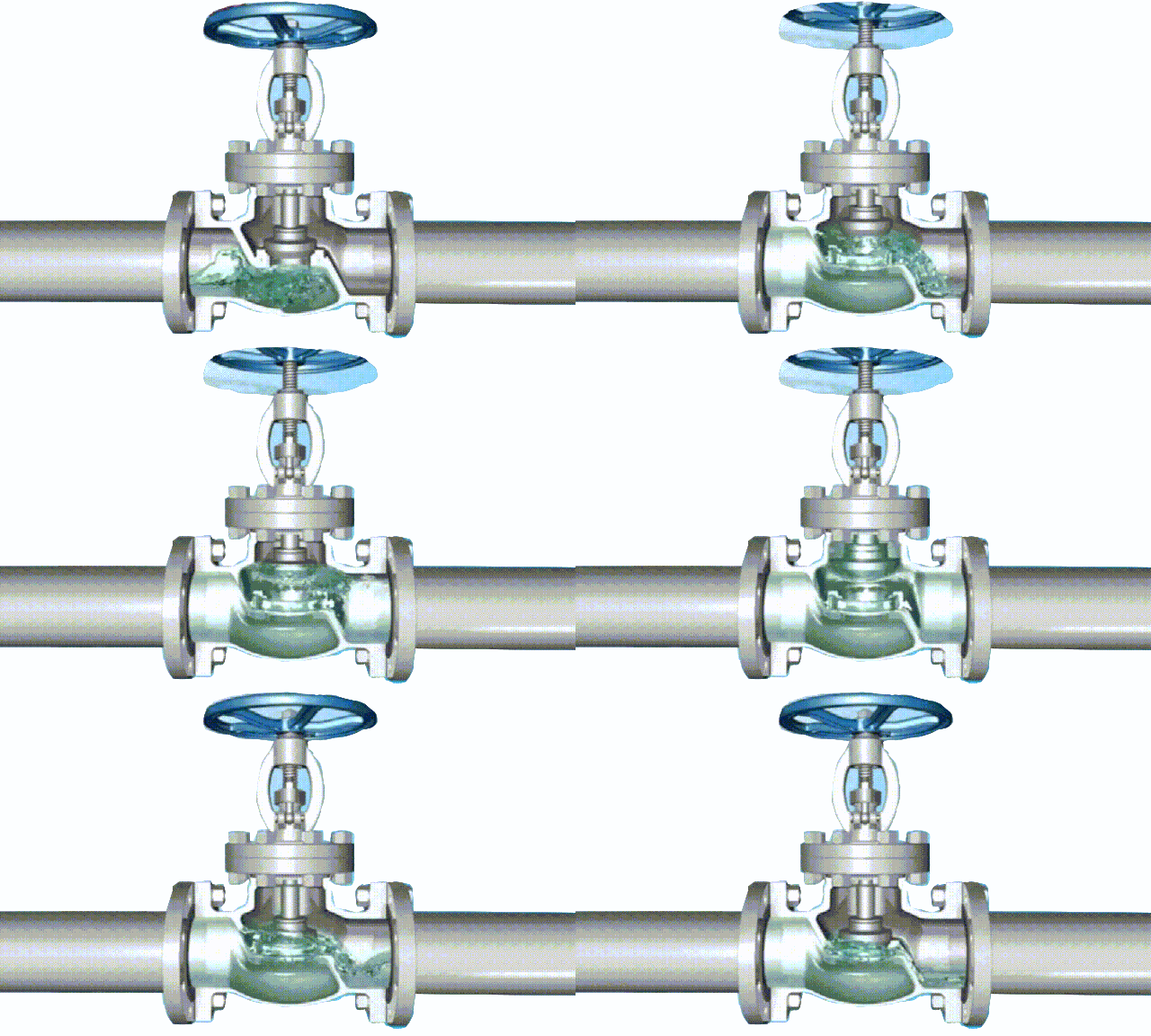
globe cut-off valve working diagram-3D GIF animated presentation

globe cut-off valve working diagram-3D GIF animated presentation

To put it simply, the principle of the globe valve is to use the torsion of the valve stem to give a downward pressure on the sealing surface, and rely on the pressure of the valve stem to make the disc sealing surface and the valve seat sealing surface closely fit to prevent the inflow of the medium or adjust the flow rate of the medium. . The opening and closing part of the stop valve is a cylindrical valve disc, the sealing surface is flat or conical, and the valve disc moves linearly along the center line of the fluid. The movement mode of the valve stem includes a lifting rod type (the valve stem is raised and lowered, and the hand wheel does not lift), and there is also a lifting rotating rod type
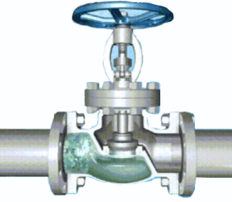
Schematic diagram of shut-off valve (closed state)

Schematic diagram of shut-off valve (closed state)

(the hand wheel and the valve stem rotate and lift together, and the nut is set on the valve body). The globe valve is a forced sealing valve, so when the valve is closed, pressure must be applied to the disc to force the sealing surface to not leak.

The working principle of the stop valve:
We assume that there is a pipe with a lid. Water flows in from the bottom of the pipe and flows out toward the nozzle. The lid of the outlet pipe is equivalent to the closing part of the shut-off valve. If the pipe lid is lifted up by hand, the water will flow out. When the cap is closed, the water stops flowing, which is equivalent to the working principle of a shut-off valve.

The shut-off valve relies on rotating the hand wheel to make the valve stem rise and fall, and drive the valve disc to make a linear displacement parallel to the flow direction of the medium to achieve the purpose of opening and closing. The handwheel rotates in a clockwise direction, and the working medium enters from the channel under the valve disc. At this time, the applied sealing force must be equal to or greater than the sum of the required specific pressure generated on the sealing surface and the upward force of the medium.
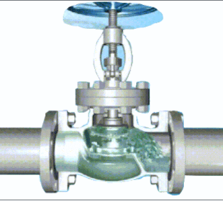
Schematic diagram of shut-off valve (open state)

Schematic diagram of shut-off valve (open state)

Schematic diagram of shut-off valve (open state)

When the shut-off valve is opened, when the opening height of the disc is 25% to 30% of the nominal diameter, the flow has reached the maximum, indicating that the valve has reached the fully open position. Therefore, the fully open position of the shut-off valve should be determined by the stroke of the valve disc.
Note:
1. The shut-off valve only allows the medium to flow in one direction, and has directionality when installed. ,
2. The function of the shut-off valve is either 0 or 1, either through or not through. In other words, the shut-off valve is only suitable for fully open and fully closed, and adjustment and throttling are not recommended.

TH Valve is a professional manufacturer of butterfly valvegate valvecheck valveglobe valveknife gate valve, ball valve with API, JIS, DIN standard, used in Oil, Gas, Marine industry, Water supply and drainage, fire fighting, shipbuilding, water treatment and other systems, with Nominal Diameter of DN50 to DN1200, NBR/EPDM/VITON, Certificates & Approvals: DNV-GL, Lloyds, DNV, BV, API, ABS, CCS. Standards: EN 593, API609, API6D

Related knowledge:
The working principle and characteristics of the globe valve;
Electric globe valve selection and application;
The working principle of butterfly valve (picture);

Valve selection basis and selection guide

How to select the righty type of valve? the following article will give you an idea how to choose the right structure/type valve.

Nowadays, there are more and more valves on the market, the types of valves are particularly complex, and the

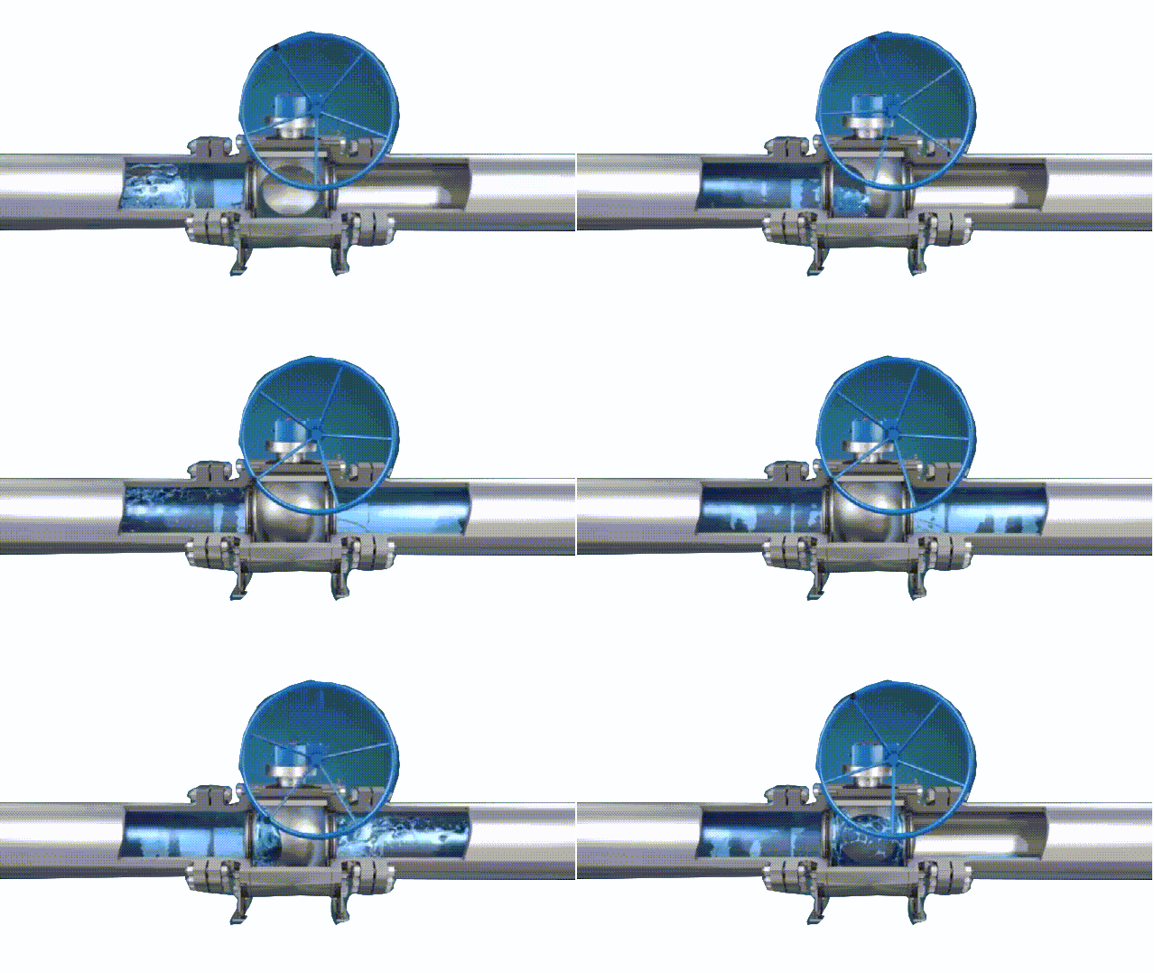
ball valve working diagram-3D GIF animated presentation

ball valve working diagram-3D GIF animated presentation

structures and materials are all different. The selection of valves is very important for the long-term operation of the device in working conditions. Improper selection of valves and users’ ignorance of valves are the source of accidents and safety threats. Nowadays, the demand for valve products in the social industry is becoming more and more extensive, and users should have a further understanding and cognition of knowledge about valves and other aspects.

There are generally two types of valve characteristics, use characteristics and structural characteristics.

Use characteristics of the valve: It determines the main use performance and use range of the valve. The

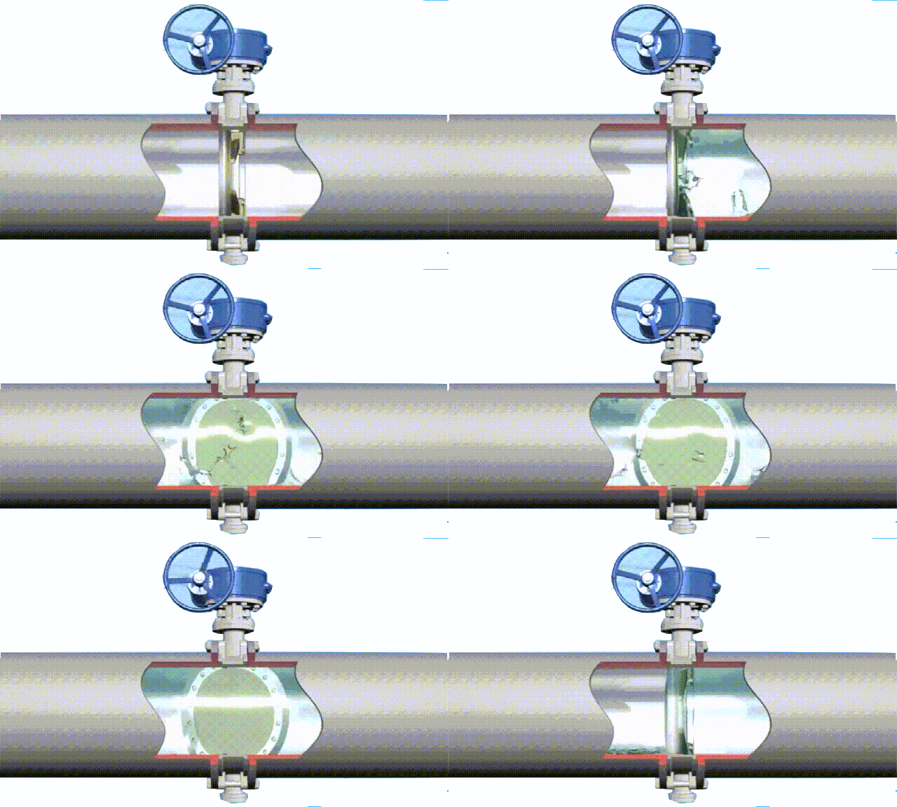
butterfly valve working diagram-3D GIF animated presentation

butterfly valve working diagram-3D GIF animated presentation

characteristics of the valve use include: valve category (closed circuit valve, regulating valve, safety valve, etc.); product type (gate valve, globe valve, butterfly valve, ball valve) Etc.); the materials of the main parts of the valve (valve body, bonnet, valve stem, valve disc, sealing surface); valve transmission mode, etc.

The structural characteristics of the valve: it determines the structural characteristics of the valve installation, repair, maintenance and other methods. The structural characteristics include: the structural length and overall height of the valve, the connection form with the pipeline (flange connection, threaded connection, clamp Connection, external thread connection, welding end connection, etc.); the form of the sealing surface (inlaid ring, threaded ring, surfacing, spray welding, valve body); valve stem structure (rotating rod, lifting

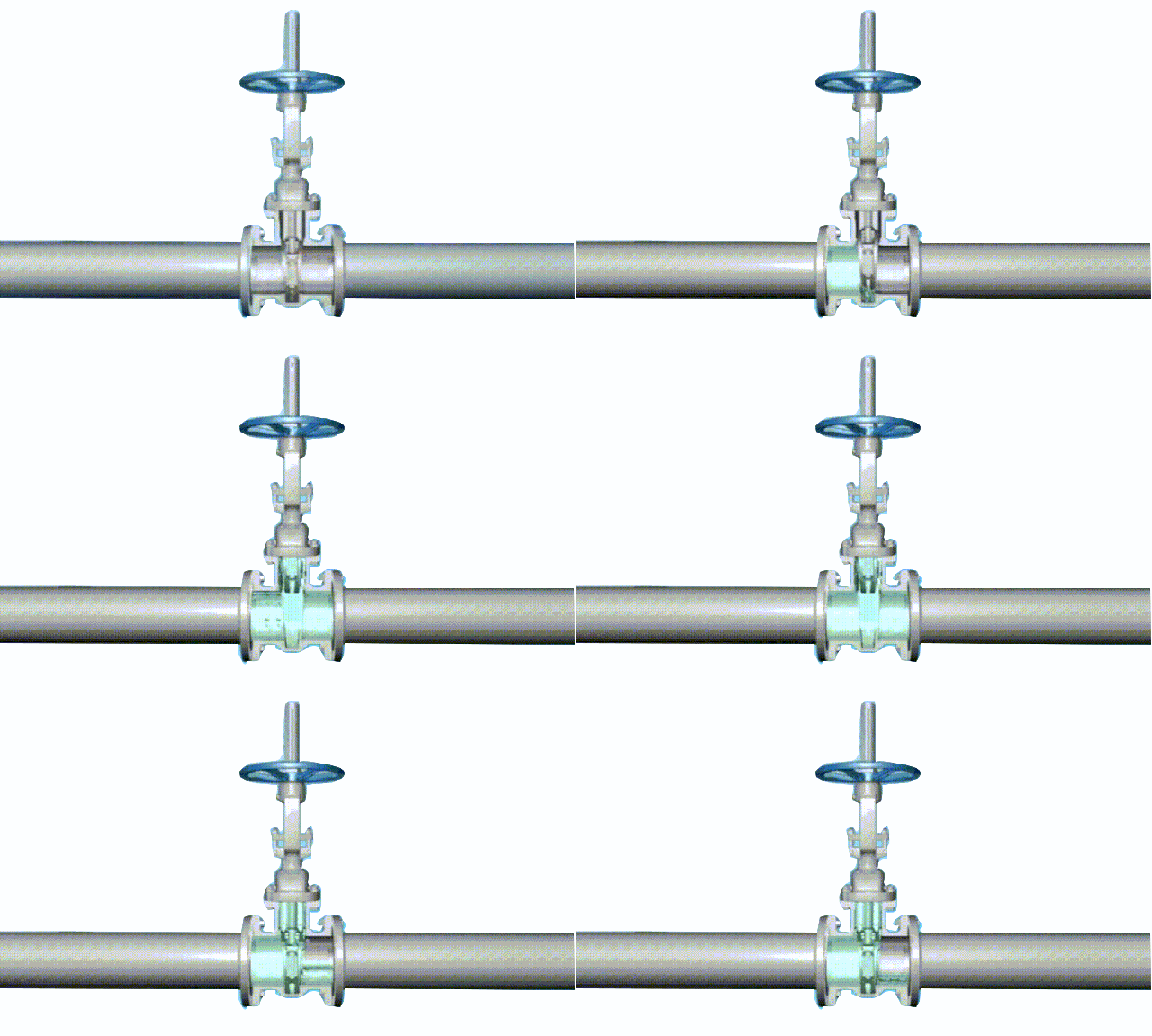
gate valve working diagram-3D GIF animated presentation

gate valve working diagram-3D GIF animated presentation

rod), etc.

Valve selection steps:
1. Clarify the purpose of the valve in the equipment or device, and determine the working conditions of the valve: applicable medium, working pressure, working temperature, etc.
2. Determine the nominal diameter and connection method of the pipe connected to the valve: flange, thread, welding, ferrule, quick installation, etc.
3. Determine the method of operating the valve: manual, electric, electromagnetic, pneumatic or hydraulic, electrical linkage or electrohydraulic linkage, etc.
4. Determine the material of the valve housing and internal parts according to the medium, working pressure and

globe cut-off valve working diagram-3D GIF animated presentation

globe cut-off valve working diagram-3D GIF animated presentation

working temperature conveyed by the pipeline: gray cast iron, malleable cast iron, ductile iron, carbon steel, alloy steel, stainless acid-resistant steel, copper alloy, etc.
5 Select the type of valve: closed circuit valve, regulating valve, safety valve, etc.
6. Determine the valve type: gate valve, globe valve, ball valve, butterfly valve, throttle valve, safety valve, pressure reducing valve, steam trap, etc.
7. Determine the parameters of the valve: For automatic valves, first determine the allowable flow resistance, discharge capacity, back pressure, etc., according to different needs, and then determine the nominal diameter of the pipeline and the diameter of the valve seat hole.
8. Determine the geometric parameters of the selected valve: structural length, flange connection form and size, valve height dimension after opening and closing, connecting bolt hole size and number, overall valve outline size,

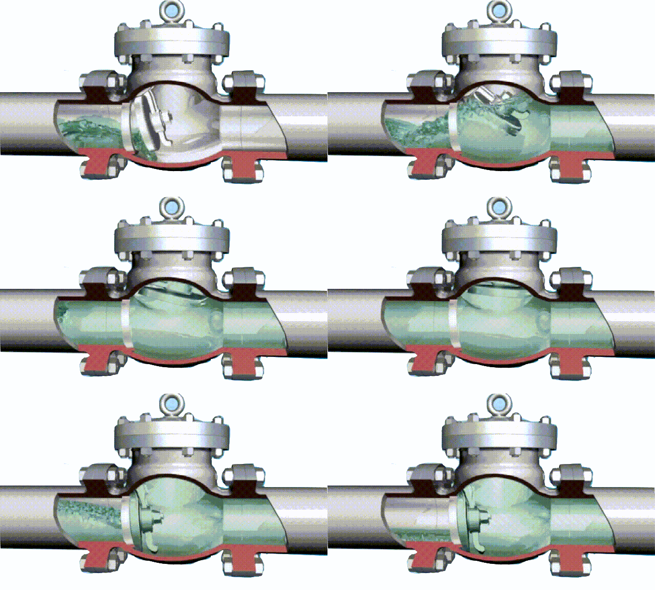
tilting disc swing check valve working diagram-3D GIF animated presentation

tilting disc swing check valve working diagram-3D GIF animated presentation

etc.
9. Use existing information: valve product catalog, valve product sample, etc. to select appropriate valve products.

Basis for valve selection:
1. The purpose, operating conditions and operation control mode of the selected valve.
2. The nature of the working medium: working pressure, working temperature, corrosion performance, whether it contains solid particles, whether the medium is toxic, whether it is flammable or explosive medium, the viscosity of the medium, etc.
3. Requirements for valve fluid characteristics: flow resistance, discharge capacity, flow characteristics, sealing level, etc.
4. Requirements for installation dimensions and external dimensions: nominal diameter, connection to the pipeline and connection dimensions, external dimensions or weight restrictions, etc.
5. Additional requirements for the reliability and service life of valve products and the explosion-proof performance of electric devices. (Note when selecting parameters: If the valve is to be used for control purposes, the following additional parameters must be determined: operation method, maximum and minimum flow requirements, pressure drop for normal flow, pressure drop when closed, maximum and minimum inlets of the valve Pressure.)

According to the above-mentioned basis and steps for selecting valves, the internal structure of various types of valves must be understood in detail when selecting valves reasonably and correctly, so that the correct choice can be made on the preferred valve. The ultimate control of the pipeline is the valve. The valve opening and closing parts control the flow mode of the medium in the pipeline. The shape of the valve flow channel makes the valve have a certain flow characteristic. This must be considered when selecting the most suitable valve for the pipeline system.