What is butt welding? (4)- flash butt welding
2. Resistance and heating of flash butt welding
The contact resistance Rc during flash butt welding is the total resistance of the liquid metal lintel between the end faces of the two workpieces, and its size depends on the number of lintels and their cross-sectional area at the same time. The latter two are related to the cross-sectional area of the workpiece, the current density and the
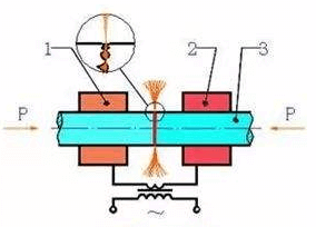
flash butt welding-schematic diagram
approach speed of the two workpieces. With the increase of these three, the number of lintels and their cross-sectional area simultaneously existing increases, and Rc will decrease.
The Rc of flash butt welding is much larger than that of resistance butt welding, and it exists throughout the flashing stage. Although its resistance value gradually decreases, it is always greater than the internal resistance of the workpiece. Rc does not disappear completely until the upsetting starts. Figure 14-5 shows the general law of Rc, 2Rω and R changes during flash butt welding. The gradual decrease in Rc is due to the increase in the approach speed of the workpiece as the end surface temperature increases during the flashing process, and the number and size of the lintels increase accordingly.
Because Rc is large and there is the entire flashing stage, the heating of the joint during flash butt welding mainly depends on Rc.
Three, flash butt welding welding cycle, process parameters and workpiece preparation
1, welding cycle
The welding cycle of flash butt welding is shown in 14-7, and the reset time in the figure refers to the time from loosening the workpiece to returning to the original position. There are two preheating methods: resistance preheating and flashing preheating. The figure (b) uses resistance preheating.
2, process parameters
The main parameters of flash butt welding are: extension length, flash current, flash flow, flash speed, upsetting flow, upsetting speed, upsetting pressure, upsetting current, clamping force, etc. Figure 14-8 is a schematic diagram of each flow rate and extension length of continuous flash butt welding. The following describes the influence of various process parameters on welding quality and the principles of selection:
(1) Elongation length l0 is the same as resistance butt welding, l0 affects the temperature distribution along the axial direction of the workpiece and the plastic deformation of the joint. In addition, with the increase of l0, the impedance of the welding circuit increases, and the required power also increases. Under normal circumstances, bar and thick arm tube l0=(0.7-1.0)d, d is the diameter of the round bar or the side length of the square bar.
For thin plates (δ=1-4mm), in order not to lose stability during upsetting, generally l0=(4-5)δ.
When different metals are butt welded, in order to make the temperature distribution on the two workpieces consistent, usually the metal with poor electrical and thermal conductivity should be smaller. Table 1 is the l0 reference value for flash butt welding of different metals.
(2) The flash current If and the upsetting current Iu If depend on the cross-sectional area of the workpiece and the current density jf required for the flash. The size of jf is related to the physical properties of the welded metal, flashing speed, the area and shape of the workpiece section, and the heating state of the end surface. In the flashing process, as vf gradually increases and contact resistance Rc gradually decreases, jf will increase. During the upsetting, Rc disappears quickly, and the current will increase sharply to the upsetting current Iu. When welding large-section steel parts, in order to increase the heating depth of the workpiece, a smaller flash speed should be used, and the average jf used generally does not exceed 5A/mm2. Table 2 shows the reference values of jf and ju for flash butt welding of workpieces with a cross-sectional area of 200-1000mm2.
The magnitude of the current depends on the no-load voltage U20 of the welding transformer. Therefore, in actual production, the secondary no-load voltage is generally given. When selecting U20, in addition to considering the impedance of the welder circuit, when the impedance is large, U20 should be increased accordingly. When welding large-section workpieces, the method of adjusting the secondary voltage in stages is sometimes used. At the beginning, a higher U20 is used to excite the flash, and then it is reduced to an adaptive value.
(3) Flash flow rate δf The flash flow rate should be selected so that there is a molten metal layer on the end of the workpiece at the end of the flash, and the plastic deformation temperature is reached at a certain depth. If δf is too small, the above requirements cannot be met, which will affect the welding quality. If δf is too large, it will waste metal materials and reduce productivity. When choosing δf, you should also consider whether there is preheating, because the δf of preheating flash butt welding can be 30-50% smaller than continuous flash butt welding.

